Amplification (OPAMP) and Digitization (ADC)
Two questions we would discuss in this post:
- When the sensors are working and sending out signals, in general, the signals from the sensors do not have suitable characteristic for display for analysis. They might have low amplitude or being noisy. How do we make it useful?
- The analog signals are continuous, how do we let the computer handle that since it is not continuous?
Amplification
How to amplify the data?
- We can use Operational Amplifier, or OPAMP in short. It is an integrated circuit (IC) that amplifies the difference in voltage between two inputs. The motivation behind it is that sometimes the signal is too small, we amplify the signal like zoom-in to details to see more.
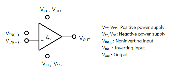
$V_{OUT} = A\cdot(V_{IN(+)}-V_{IN(-)})$
- Where $A$ is a gain, the value of $A$ is a property of the OPAMP that given to users.
Output Saturation
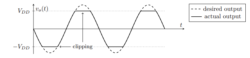
- When the output voltage implied by the circuit exceed the possible range, the op-amp is said to saturate, and it just outputs its maximum or minimum possible voltage instead.
- For $A\cdot(V_{IN(+)}-V_{IN(-)}) > V_{CC} \rightarrow V_{OUT}=V_{CC}$
- For $A\cdot(V_{IN(+)}-V_{IN(-)}) < V_{EE} \rightarrow V_{OUT}=V_{EE}$
Common circuits of OPAMP:
- More in lecture notes from Stanford
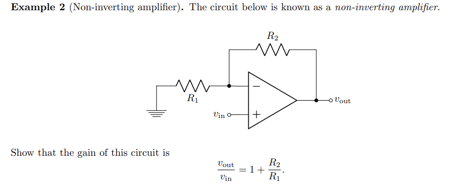
- Example: Non-inverting Amplifiers
- It is called non-inverting AMP because the voltage changes in same direction as input.
- It is called non-inverting AMP because the voltage changes in same direction as input.
- Since $v_{out} = A\cdot(v_{in(+)}-v_{in(-)}) \rightarrow \frac{v_{out}}{A} = v_{in(+)}-v_{in(-)}$, when A is very large, we have $v_{in(+)}=v_{in(-)}$.
- Here consider $v_{in(+)}$ is the sensor, and the upper half is a voltage divider. Then we know that $v_{in(-)} = \frac{R_1}{R_2+R_1}v_{out} = v_{in(+)}$
- Derive it further, we have the equation shown in the image, new gain $(1+ \frac{R_2}{R_1})$. Now we can control how much we want to amplify the input, by our choice of resistors.
Digitization
Digitization is the process of changing from analog to digital form.
Since the world is continuous but the computers can only perform operations on digital or discrete values, we need to convert analog to digital signal so the computer can handle it.
Analog-to-digital Converter (ADC)
Analog-to-digital converter or ADC in short, is a system that converts a continuous-time and continuous-amplitude analog signal to a discrete-time and discrete-amplitude digital signal.
Building ADCs
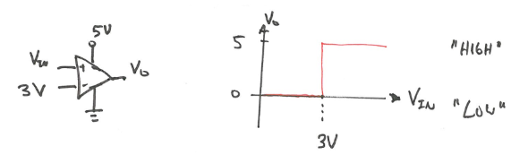
- Recall that OPAMPs have a very narrow linear range before it saturates, such that we can think it as a “jump”. And we can exploit this narrow linear range to build a voltage comparator.
- Note here $V_{REF}$ is where $v_{in(+)} = v_{in(-)}$
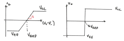
For example, if we want to label a signal as either being smaller or larger than 3V with a margin of error of ±0.5V. Then we will have $V_0 = 0V$ for $V_{IN}<3V$ and $V_0 = 5V$ for $V_{IN}>3V$. This voltage comparator gives us a binary response, which is a 1 bit ADC, transforms analog signal to digital.
- Now we can stack a bunch of these together to get more complex ADC architectures.
Measuring analog signals
![]()
ADCs first sample the signal, then quantify it to determine the resolution of the signal, and finally set binary values and send it to the system to read the digital signal. Two important aspects of the ADC are its sampling rate and resolution.
Sampling rate: The sampling rate is measured by using “samples per second”. This simply means how many samples or data points it takes within a second. The more samples the ADC takes, the higher input frequencies it can handle.
Resolution: The smallest change in an analog signal that will result in a discrete output. The resolution of the ADC is the number of bits it uses to digitize the input samples.
- step size $ = \frac{V_{REF}}{2^N}$
- $V_{REF}$ is the voltage range
- N is the bit length of the ADC
$2^N$ is the total # of discrete values. 2 comes from the binary representation. 1 bit can represent 2 numbers {0, 1}, 2 bits can represent 4 numbers {00, 01, 10, 11}.

- For example: a 4-bit ADC with a 0-4V range will give $2^4 = 16$ discrete values with $\Delta V = 0.25V$.
To improve the accuracy of the ADC we can:
- Increase the resolution (more bits) to improve the measurement of signal amplitude
- Increase sampling rate (clock speed) to improve temporal resolution
Common ADCs
Flash ADC
- MATLAB doc
- An N-bit flash ADC comprises of a resistive ladder that contains $2^N$ resistors and $2^{N-1}$ comparators.
- Pro: it is simple and it is fast; Con: too many components and it is expensive so it is not so common to use
Successive Approximation ADC
Using DAC, we can build something called successive approximation (SAR) ADC. It is very common to use. It is easy to build but the speed is slow.
- The opposite of ADC - DAC (Digital-to-analog converter). It takes an input voltage $V_{ref}$ and a command from a controller(computer), outputs a voltage $V_o$ at a resolution of N-bits.

Dual-slope ADC (DS-ADC)
What unique about this type of ADC is that it uses integrator.
Delta-sigma ADC
Delta-sigma ADC has a more complex structure compare to the other 3 above, but it improves meausrement performance. Delta-sigma ADCs implement oversampling, decimation filtering, and quantization noise shaping to achieve high resolution and excellent antialiasing filtering.

This post has part of my notes from the class I am taking “CEE 575 Infrastructure Sensing” offered by Prof. Branko Kerkez at University of Michigan.