Capacitive Sensors
Capacitor
Capacitor is a circuit element that stores charges, sometimes called “charge buckets.”
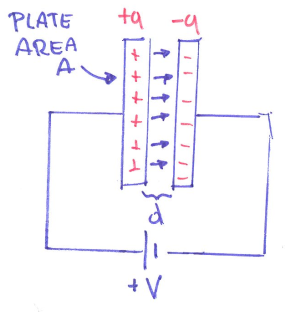
As shown in the image, each plate receives an equal but opposite amount of charge. The amount of the charge is proportional to the area A and the distance d. When the area gets larger, or the distance gets closer, the amount of charges increase.
- where q is number of charges, V is voltage, and C is capacitance with unit
coulomb/volt=farad.
Dielectric constant: When filling the space between plates with non-conductive material, we have a new capacitance $C_{new}=k\cdot C_{vacuum}$ where k is the dielectric constant, it is a material property.
The capacitance of a capacitor is given by:
\[C=\frac{k \cdot \varepsilon_0 \cdot A}{d}\]- where $\varepsilon_0 = 8.85\times 10^{-12} $ is dielectric constant of vacuum, k is a dielectric constant of the material in between.
Capacitive sensor
Definition: A capacitive sensor converts changes in position, geometry or properties of a dielectric into electric signals.
\(C = f(A, d, k)\) where A is area, d is distance, k is dielectric property (the thing in between the two plates)
Accelerometer
Force - displacement
- Displacement is a direct indicator of movement
- Displacement is indirect indicator of other variables such as force/pressure. In other words, if you can measure displacement, you can measure force.
Lateral movement
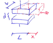
- C = f(A, d, k)
- Motion of top plate causes linear change in capacitance.
- From $C_0=\frac{k\varepsilon_0 A}{d}$ to $C=\frac{k\varepsilon_0 W(L-x)}{d}$
- However, we have to guarantee that lateral motion does not affect the separation between plates, such design is not good for small displacements and hard to implement.
Plate separation
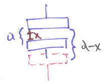
- C = f(A, d, k)
- Most sensors are based on a change in the plate separation d.
- From $C_0=\frac{k\varepsilon_0 A}{d}$ to $C=\frac{k\varepsilon_0 A}{d-x}$
- -x or +x is about how you define the reference, here we have the sensor moving downward
- The change is non-linear, but for small changes x we can approximate through the use of taylor series. Then for the capacitance we can get: $C \approx \frac{k\varepsilon_0 A}{d}[1-\frac{x}{d}+\frac{x^2}{d^2}]$
- For $x \ll d$ the change in C is linear with change in displacement x.
- The non-linearity appears in the higher order terms: $\frac{x^2}{d^2}$, etc., and could be a concern if we want high accuracy for displacement.
Improvement: differential displacements
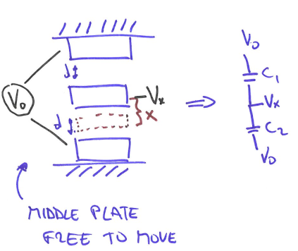
- We change the design to 2 fixed plates and the middle plate is free to move.
If we are able to measure $\Delta C=C_2-C_1$, then:
\[\Delta C=\frac{k\varepsilon_0 A}{d}[1+\frac{x}{d}+\frac{x^2}{d^2}]-\frac{k\varepsilon_0 A}{d}[1-\frac{x}{d}+\frac{x^2}{d^2}]=\frac{k\varepsilon_0 A}{d}\frac{2x}{d}\]- The non-linearity is subtracted away, and this design is good for accuracy purpose.
- However, how do we measure $\Delta C$, how do we subtract one capacitor from another?
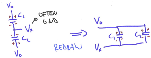
- The circuit above has two capacitors in parallel. When connect to the power, the change of the total capacitance would be $\Delta C = C_1+C_2$, which is not subtraction we are looking for.
Solution #1 opposing D.C. voltage
DC stands for direct current. In direct current, the voltage is always constant, and the electricity flows in a certain direction.
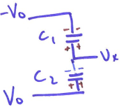
- Charges cancel -> $V_x =0 $ when plate does not move
- When middle plate moves -> $V_x$ changes sign depending on direction if the place move up or down. Now we have the subtraction we want.
- However, the voltages will saturate very quickly again after plate moves, such that it is hard to measure.
Solution #2 A.C. source
AC stands for alternating voltage. In alternating current, the voltage periodically changes from positive to negative and from negative to positive, and the direction of the current also periodically changes accordingly.
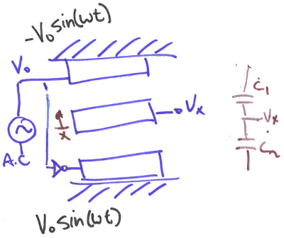
- Set $\omega \approx 1$MHz very FAST because we don’t want the capacitors to settle down.
- If middle plate is centered, then currents cancel -> $V_x=0$
- If plate move, charge buildup does not remain constant -> $V_x$ changes.
- Substitute $C=\frac{k \cdot \varepsilon_0 \cdot A}{d} $ to above equation based on change in d or A. For the example’s situation ($\Delta d$), we have the result:
- Note there that $V_0$ is alternating.
Spring mass damper system
Now we relate voltage changes with the displacement changes linearly, how do we build an accelerometer from it?
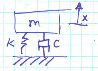
- A mass m is attached to a spring and a damper
- Hook’s law: spring force $F_s=-kx$, damping force $F_d=-c \frac{dx}{dt}=-c \dot{x}$
- k is spring constant, c is damping constant.
- Newton’s law: $F=ma$
- Put everything together we have:
Divide by m to get common form we have $\ddot{x}+ \frac{c}{m} \dot{x}+\frac{k}{x}x = 0$. Then let:
- natural frequency $\omega_0=\sqrt{\frac{k}{m}}$
- damping ratio = $\zeta=\frac{c}{2\sqrt{km}}$
Thus, we have
\[\ddot{x}+2\zeta \omega_0 \dot{x}+\omega_0^2x=0\]Now we can build something to measure acceleration. We hook the middle plate to a mass on a spring like in the image.
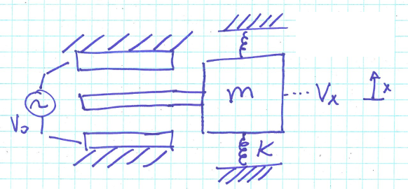
- Ignoring damping we have $\ddot{x}+\frac{k}{x}x = 0$. Then $a=-\ddot{x}=\frac{F_k}{m}=\frac{kx}{m}=\frac{kd}{m}\frac{V_x}{V_0}$
- Now we have a relation between output voltage $V_x$ and the acceleration $a$. Meaning that we have built an accelerometer.
How to measure capacitance
We have explored how capacitance can be used to measure movement, but how do we measure capacitance?
Method #1 RC-based
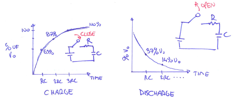
When a capacitor is placed in series with a resistor, we can get some useful relationships. It can be shown that the voltage across a capacitor in an RC (resistor+capacitor) circuit is given by:
\[V(t)=V_0(1-e^\frac{-t}{RC})\]- R is resistance, C is capacitance
- $\tau = R\cdot C$ where $\tau$ is a time constant. Measure $\tau$ can help to measure C
Method #2 Charge-based
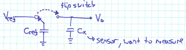
- Rely on the ability of capacitor to hold charge
- $C = \frac{Q}{V}$
Details:
- Charge $C_{ref} \rightarrow Q=C_{ref}\cdot V_{ref}$
- Flip the switch to the right, the charge Q would not change
- Flip left: $Q = C_{ref}\cdot V_{ref}$; Flip right: $Q=(C_{ref}+C_x)\cdot V_o$
- From the equations above, we have:
- Then we can get $C_x$ by measuring $V_o$ after flipping switch to the right.
- Note that this method may be prone to error because the actual switch can inject charge into the system.
Method #3 Series R-C bridge
Definition: Impedance is the opposition to alternating current presented by the combined effect of resistance and reactance in a circuit.
RC-Impedance
- A series RC circuit will offer the opposition to the current flow due to both the resistor and capacitor. Let, the alternating voltage of angular frequency $\omega$ is applied across the series RC combination. Then the formula of the impedance of RC circuit is $z = R+\frac{1}{j\omega C}$ or $z = R-\frac{j}{\omega C}$.
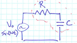
- $V = z \cdot i$
Measuring capacitance
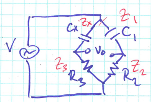
- Here we have a series R-C bridge
- When $V_0=0$ it can be shown that $z_1\cdot z_3=z_2\cdot z_x$
- Then substitute $z = R-\frac{j}{\omega C}$ into the equation above, we have
- Adjust $C_1$ until $V_0=0$ then we can calculate $C_x$ since we know $C_1, R_2, R_3$
This post is my notes from the class I am taking “CEE 575 Infrastructure Sensing” offered by Prof. Branko Kerkez at University of Michigan.