Forward Kinematics
Robot Kinematics:
- Goal: Given the structure of robot arm, we can compute
- Forward Kinematics: inferring the pose of the end-effector, given the state of each joint.
- Inverse Kinematics: inferring the joint states that are necessary to reach a desired end-effector pose.
Kinematic Foundations
Here is an example of an articulated robot. Articulated robot is a robot with rotary joints (e.g. a legged robot or an industrial robot). Articulated robots can range from simple two-jointed structures to systems with 10 or more interacting joints and materials.
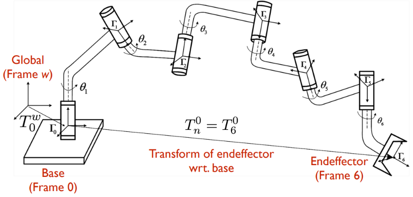
Forward kinematics is many-to-one mapping of robot configuration to reachable workspace end effector poses.
- Workspace is a 3D space defined in the global frame.
- Configuration $(q)$ is the state of all joints in the kinematics chain, $q = {q_1, \cdots, q_n}$
- Joint $(q_i)$ relates the motion of one link (child link) with respect to another link (parent). Joint motion only affects the child link where its state. In the image above, Link 1 $\Gamma_1$ is a child of joint 1 $\theta_1$, and Link 0 $\Gamma_0$ is the parent of joint 1.
- $q_i=\theta_i$ if it is a revolute joint
- $q_i = d_i$ if it is a prismatic joint
- Kinematic chain connects
N+1links together byNjoints, with a coordinate frame on each link. - Configuration space (C-space): the space of all possible configurations
- DOF (Degree of freedom) of a robot is the dimension of the robot’s C-space, which is the minimum number of real numbers needed to represent the robot’s configuration. A rigid body in three-dimensional space has six degrees of freedom (DOFs).
- Position: motion along the x, y, z axis
- Orientation: rotation around x(roll), y(pitch), z(yaw).
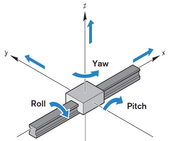
- Right-hand rule
| Coordinate conventions | A rotating body |
|---|---|
 |
 |
- Note that different application has different coordinate convention
- To find the rotation direction, the right thumb pointing in the positive direction of the axis, and right fingers curled in the direction of rotation
The goal of forward kinematics is inferring the pose of the end effector given the state of each joint, thus we need to relate all the link’s own frame with each other, because every link considers itself to the center of the universe.
Then new questions arise, 1) how to represent the transforms? and 2) how to compute the transform to end effector?
First, we want to define the kinematics of a robot. Traditionally, we have Denavit-Hartenberg Convention. In recent years, we have URDF convention.
- URDF stands for Unified Robot Description Format.
- URDF defined by its implementation in ROS (“Robot Operating System”), and ROS uses URDF to define the kinematics of an articulated structure. The structure is specified through XML. Kinematics represented as tree with links as nodes, joint transforms as edges.
Homogeneous transformation matrix
Homogeneous Coordinates
Homogeneous Coordinates are a system of coordinates used in projective geometry, just as Cartesian coordinates are used in Euclidean geometry.
- Here is a great article of explanation and illustration.
- To make 2D homogeneous coordinates, we append an additional variable $w$ to the Cartesian coordinates $(X,Y)$, then we have $(x,y,w)$ in homogeneous coordinates. And reversely, the original $(X,Y)$ can be represented as $(\frac{x}{w}, \frac{y}{w})$. The value of $w$ would affect the size of the image.
- Note here that the (x,y,w) is not a point in three dimensions like the Cartesian (x,y,z)
- Motivation: In Euclidean space, two parallel lines will never intersect, but in projective space, two parallel lines can meet at the point of infinity. The third coordinate exists for one purpose only, and that is to add some points to the domain, namely, points at infinity. Sometimes, it is useful to think in terms of projective geometry.
- For example, when we want to do translation and rotation at the same time. But translate operation is represented by matrix addition rather then multiplication, homogeneous coordinates will be helpful here.
- In 3D world, $w$ value works exactly the same as it does in 2D. A useful convention for 3D homogeneous coordinates is that we always set $w=1$ where the image doesn’t shrink or grow.
- To make 2D homogeneous coordinates, we append an additional variable $w$ to the Cartesian coordinates $(X,Y)$, then we have $(x,y,w)$ in homogeneous coordinates. And reversely, the original $(X,Y)$ can be represented as $(\frac{x}{w}, \frac{y}{w})$. The value of $w$ would affect the size of the image.
- A Youtube video dives deeper into the topic.
2D space
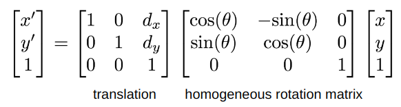
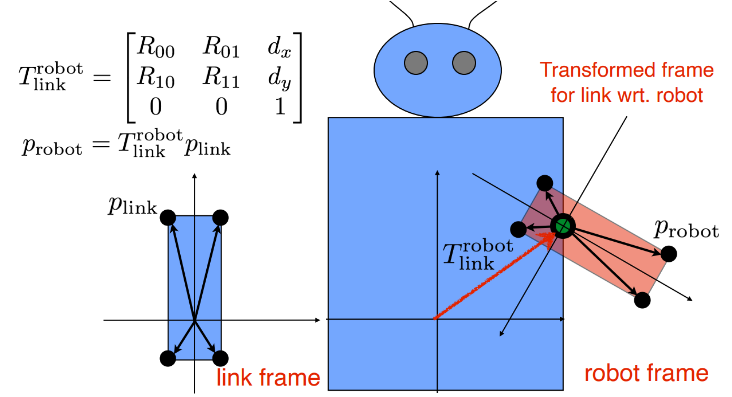
Composition of Rotation and Translation: by modifying both rotation matrix and translation vector into homogeneous coordinates, we are able to combine them into one single homogeneous transformation matrix, or a transformation matrix for short. Read from the right to left, we first do rotate and then translate.
- Why not translate then rotate? Because $M = R\cdot T$ is different with $M = T\cdot R$.
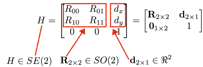
- Special Euclidean group in two dimensions SE(2), where SO(2) means the group of rotations in two dimensions
Special Euclidean group, often denoted SE(n), whose elements are called rigid motions or Euclidean motions, that preserve the Euclidean distance between every pair of points. They comprise arbitrary combinations of translations and rotations, but not reflections.
Example: Now we want to put an arm on the robot. By multiplying the transform matrix $T_{link}^{robot}$, we can find where the arm should at in the frame of the robot. If we analyze it step by step, firstly, rotate link frame by R, then translate link frame by d.
3D space
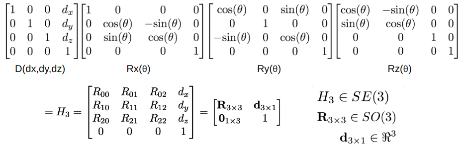
- Here is the 3D homogeneous transform matrix. It consists of a translation matrix, and 3 rotation matrices relate to rotate along x,y,z axis. If you are familiar with pinhole camera model, this is the extrinsic matrix to map points from the world frame to the camera frame.
Axis-Angle Rotation and Quaternions
In the transformation matrix above, we use Euler Angles to express the rotation around x(roll), y(pitch), z(yaw).
- However, it is problematic when rotate about each axis in order $R = R_x(\theta_x)R_y(\theta_y)R_z(\theta_z)$. Something called Gimbal lock would occur when 2 axes are rotated into alignment. It will reduce 3 DOFs to 2 based on the axis order.
Alternatives to present rotations:
- Axis-angle representation which only valid in 3D space. It parameterizes a rotation in a three-dimensional Euclidean space by two quantities: a unit vector $e$ indicating the direction of an axis of rotation, and an angle $\theta$ describing the magnitude of the rotation about the axis.
- Example: (axis, angle) = ($[0, 0, 1]^T, \frac{\pi}{2}$), rotate along z-axis by 90 degrees
- Quaternion, which is useful for describing orientation and computing rotations in 3D world for robotics.
- It is just a different way to describe the orientation of a body, not meant to be read directly, namely not as intuitive as the Euler angle. Quaternions are more numerically robust, so if we have access to it, we should choose it over Euler angles.
- ROS’s tf library has function
from tf.transformations import quaternion_from_eulerwhich can help us to do the conversion conveniently.
Quaternion conversion
- Calculate quaternion from axis-angle representation:
1
2
3
4
5
6
7
8
9
10
11
12
13
14
15
16
17
18
19
20
import math

def quaternion_from_axis_angle(axis, angle):
	"""
	Convert axis angle representation to quaternion representation

	Return [x, y, z, w] where w is the real number
	"""
	q = [0]*4
	q[0] = axis[0]*math.sin(angle/2)
	q[1] = axis[1]*math.sin(angle/2)
	q[2] = axis[2]*math.sin(angle/2)
	q[3] = math.cos(angle/2)

	return q

# Test:
axis = [0, 0, 1]
angle = math.pi/2
print(quaternion_from_axis_angle(axis, angle))
Now we have answered the question 1) how to represent the transforms?
- The answer is by using transformation matrix.
- The next question is how to compose these matrices hierarchically to compute transform wrt. world?
Matrix stack for FK computation
We need to transform along kinematic chain bringing descendants along, such that we can find where the end effector at in the world frame. The hierarchy is given by the URDF file.
- Goal: compute transform of frame at each kinematic node into the world frame.
- Approach: Compose transforms along kinematic tree using a stack data structure
- top of the stack is transform for current node
- Code: Recursively alternate between link and joint to update transform at top of stack
- start with base link and global transform
- for each link, recurse over all children
- for each joint, compose rotational and translational effects and push it into the stack
This post is part of my notes from the class I am taking “ROB 511 Advanced Robot Operating System” offered by Prof. Chad Jenkins at University of Michigan.