Inductive Sensors
Electromagnetic Induction
Electromagnetic induction: We know that a current flowing in a wire would produce a magnetic field. To increase the measurable effect of the field we can spin the wire into a coil.
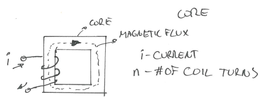
For one turn of the coil, the magnetic flux is:
\[\Phi=\frac{ni}{\mathcal{R}}\]- where $\mathcal{R}$ is the reluctance, a property of the core material. Magnetic reluctance is analogous to electrical resistance in an electrical circuit.
- $\mathcal{l}$ - total length of flux path
- A path which is followed by magnetic lines of force and in which the magnetic flux density is significant.
- $\mu_0$ - permeability of vacuum
- $\mu$ - permeability of core material
- A - cross sectional area of the coil
- where $\Phi$ is magnetic flux for one turn of the coil, unit Tesla. And $\Psi$ is the total flux, unit Weber.
Definition: The inductance L of a coil is the total flux per unit current:
\[L = \frac{\Psi}{i}=\frac{n^2}{\mathcal{R}}\]- The relationship between inductance and current is: change in current causes a measurable voltage.

Further, change in the magnetic field can induce a change in current and vice versa.
\[\frac{d\Psi}{dt} \propto \frac{di}{dt} \rightarrow V\propto \frac{d \Psi}{dt}\]Mutual Inductance
- An alternating current flow in one coil can induce a current flow in another coil.
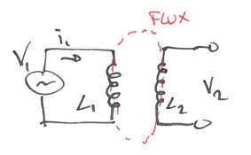
- where M is coefficient of mutual inductance.
- In general, it depends on the reluctance(distance and material between coils) with which a magnetic flux can flow between inductors.
- $i_1$ would induce another current flow $i_2$ in the RHS circuit
Usage
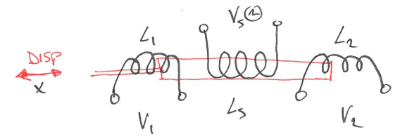
The Linear Variable Differential Transformer (LVDT)
Linear variable differential transformer is a type of electrical transformer used for measuring linear displacement (position).
The red bar is the core moving in x direction, and Vs is the source power. According to effect of mutual inductance, we know $V_1 = -M_1\frac{di_s}{dt}$ and $V_2 = -M_2\frac{di_s}{dt}$. Red bar’s change $\Delta x$ in position will cause a change in $M_1$ and $M_2$ due to reluctance changes. Thus,
\[V_0 = V_1 - V_2 = (-M_1\frac{di_s}{dt}) - (-M_2\frac{di_s}{dt}) = (M_2 - M_1)\frac{di_s}{dt}\]Why we need 2 secondary coils here? - It gives the linearity, ($M_2-M_1$) can show it’s linear. With one coil, the change in M is non-linear.
How do we measure?
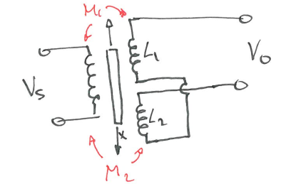
- At $x=0$, $V_0=0$, $M_1=M_2$
- Connect in open-wiring configuration
- As core moves, it will change $M_1, M_2$, this will change the induced voltages $V_1, V_2$, and the amplitude of $V_0$ is linear with $\Delta x$.
Electromagnetic Flow Meter
- Electromagnetic flow meters are comprised of a transmitter and sensor that together measure water flow.
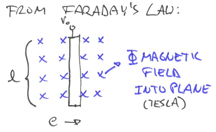
- If a conductor of length l(m) is moving perpendicular to a magnetic field $\Phi$ at a velocity e (m/s), the voltage $V_o$ is induced:
- One might more familiar with the form $V = Blv$ but they are the same.
- With Faraday’s law, we can build flow meter from it.
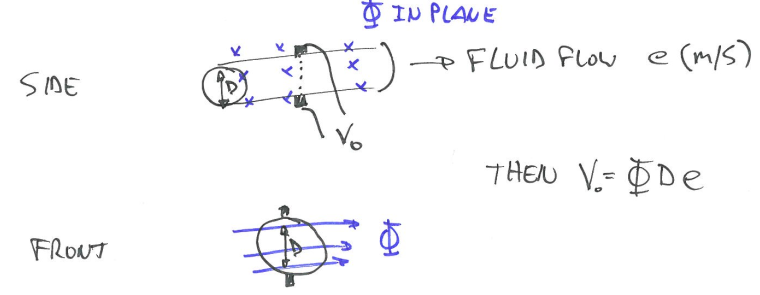
In the case of a flow meter, the conductor is the liquid. We know that
\[Q = A \cdot e \qquad A = \frac{\pi D^2}{4}\]- e is the velocity of the flow m/s
- A is the cross-sectional area of the pipe
- Q is the flow of the liquid $m^3/s$
- D is the diameter
- Measuring the voltage can help us to measure the flow, although it is very difficult to build flow meter.
Inductive-loop traffic detectors (RLC circuit)
Vehicle detection loops can detect vehicles passing or arriving at a certain point. When no car is present, the inductance of the loop is a steady, known value. When a car passes over the loop, the inductance changes. We can simplify it to a circuit like in the figure below, which is a common tool for measuring the change of an unknown inductor.
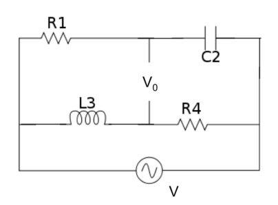
Definition: Impedance is the opposition to alternating current presented by the combined effect of resistance and reactance in a circuit.
- Impedance for a pure resistor is its resistance
- Let the capacitance of a capacitor is C and the alternating current passing through the capacitor circuit have the angular frequency $\omega$. Then the impedance experiences by the current passing through the capacitor is $z = \frac{1}{j\omega C}$
- If L is the inductance of an inductor operating by an alternating voltage of angular frequency $\omega$, then the impedance offered by the pure inductor to the alternating current is, $z=j\omega L$.
- Source
To obtain the value $L_3$, a variable capacitor $C_2$ is digitally adjusted until the bridge circuit is balanced ($V_0 = 0$). Then, it can be shown that $z_1 \cdot z_4 = z_3 \cdot z_2 $. Thus,
$R_1\cdot R_4 = (j\omega L_3)(\frac{1}{j\omega C_2})$
$ L_3 = R_1\cdot R_4 \cdot C_2 $
This is my notes from the class I am taking “CEE 575 Infrastructure Sensing” offered by Prof. Branko Kerkez at University of Michigan.