IoT Weather Station with ESP32 and BME280
In this article, I will outline the process of using the BME280 sensor module with the ESP32 as the motherboard to read temperature and humidity. At the same time, retrieve local weather using OpenWeather API. Finally, display the two sets of readings on an OLED screen.
This article is especially feasible for beginners who want to use University’s WiFi but have trouble connecting.
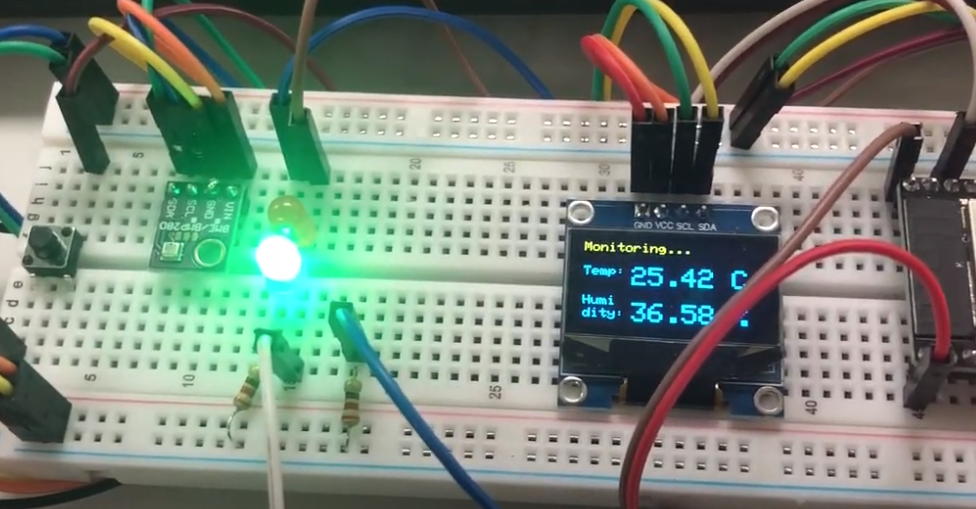
Room readings
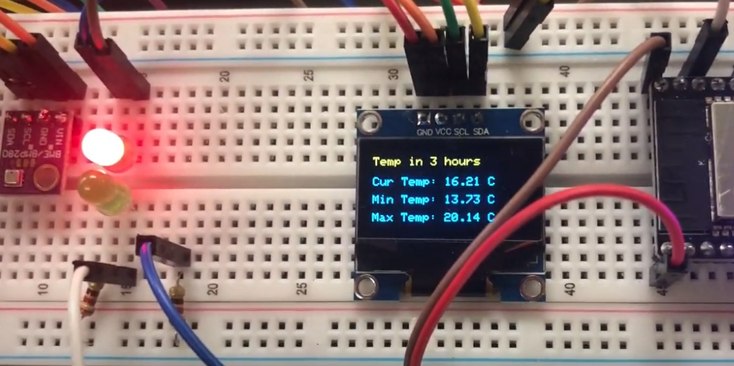
Local weather
To build such a project, the first step we need to purchase all the components we need. The list below includes all the components I have purchased for this project.
Items
- ESP32
- ESP32 is a low-cost, low-power Microcontroller with an integrated Wi-Fi and Bluetooth.
- Note that ESP32 is the chip microcontroller, espressif manufactures their own development board, but there is also other company like this one builds development board based on ESP32. So espressif’s core product is the microcontroller, anybody can create their own board if you know how to create a PCB.
- This is what I got, I personally don’t like it because the pin’s name is printed on the back so you have to refer to the manual when wiring the components.
- ESP32 is a low-cost, low-power Microcontroller with an integrated Wi-Fi and Bluetooth.
- BME280
- The BME280 sensor module reads barometric pressure, temperature, and humidity. It uses I2C or SPI communication protocol to exchange data with a microcontroller.
- Amazon - Soldering needed
- OLED Display
- Miscellanea
- LED bulbs (Green/Red), Buttons, Breadboard, Resistors (220 Ohm), Jumpwires, Pin header
- Note that all these listings are necessary for this project.
- LED bulbs (Green/Red), Buttons, Breadboard, Resistors (220 Ohm), Jumpwires, Pin header
- Optional
- Soldering station (I bought a cheap one because I want to learn how to do soldering and will use it in other projects. It is unnecessary unless you cannot find a soldering station anywhere for quick use.)
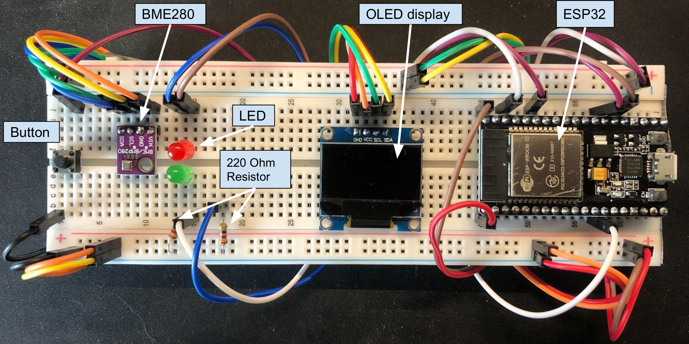
Wiring
Suggestion: implement wiring and coding at the same time for each functionality. When one feature is tested, then add more onto the board.
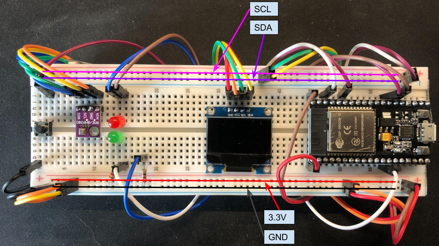
The power rails are connected as marked in the image below for simplicity.
- The upper two rails are connected to the SCL and SDA pins because both BME280 and the display need to connect to these two pins.
- The lower two rails are connected to 3.3V and Ground pin.
Now let’s look into the details.
The wiring of the display is simple. As shown in the image below, we just need to connect the 4 pins as marked on the board accordingly.
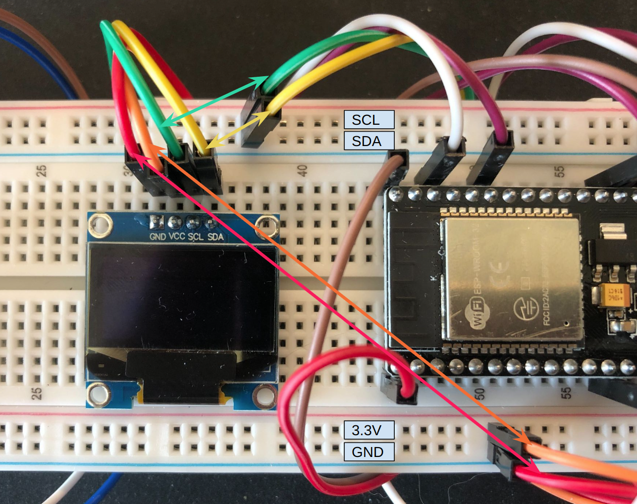
On the left-hand side, the BME280’s wiring is also directive. We need to connect the four pins accordingly same as what we did for the display.
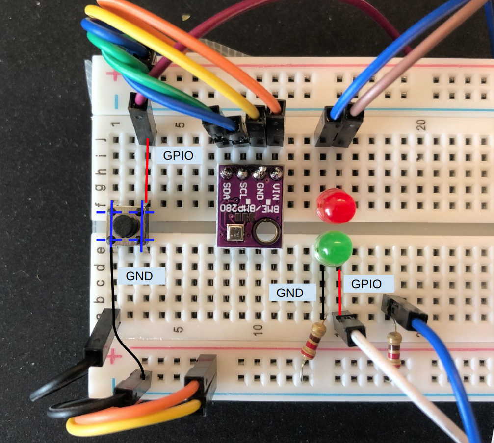
For the button, as shown in the image, the solid blue lines are interior connected, such that I put the button sits on the ravine so the two sides are isolated unless you press the button. When you press the button, the dashed line will be connected, so the board will know that you have pressed the button. Then we just need to connect one side to the ground and another side to any of the GPIO pins you’d like to use.
For the two LEDs. Let’s take the Green one as an example. Firstly, polarity matters. The positive side of the LED is called the “anode” and is marked by having a longer leg. The shorter leg is the negative side, called the “cathode.” Current flows from the anode to the cathode. You should connect the longer leg to the GPIO pin you’d like to use and the shorter leg to the ground pin. You cannot see it from the image, but that’s how it is connected beneath.
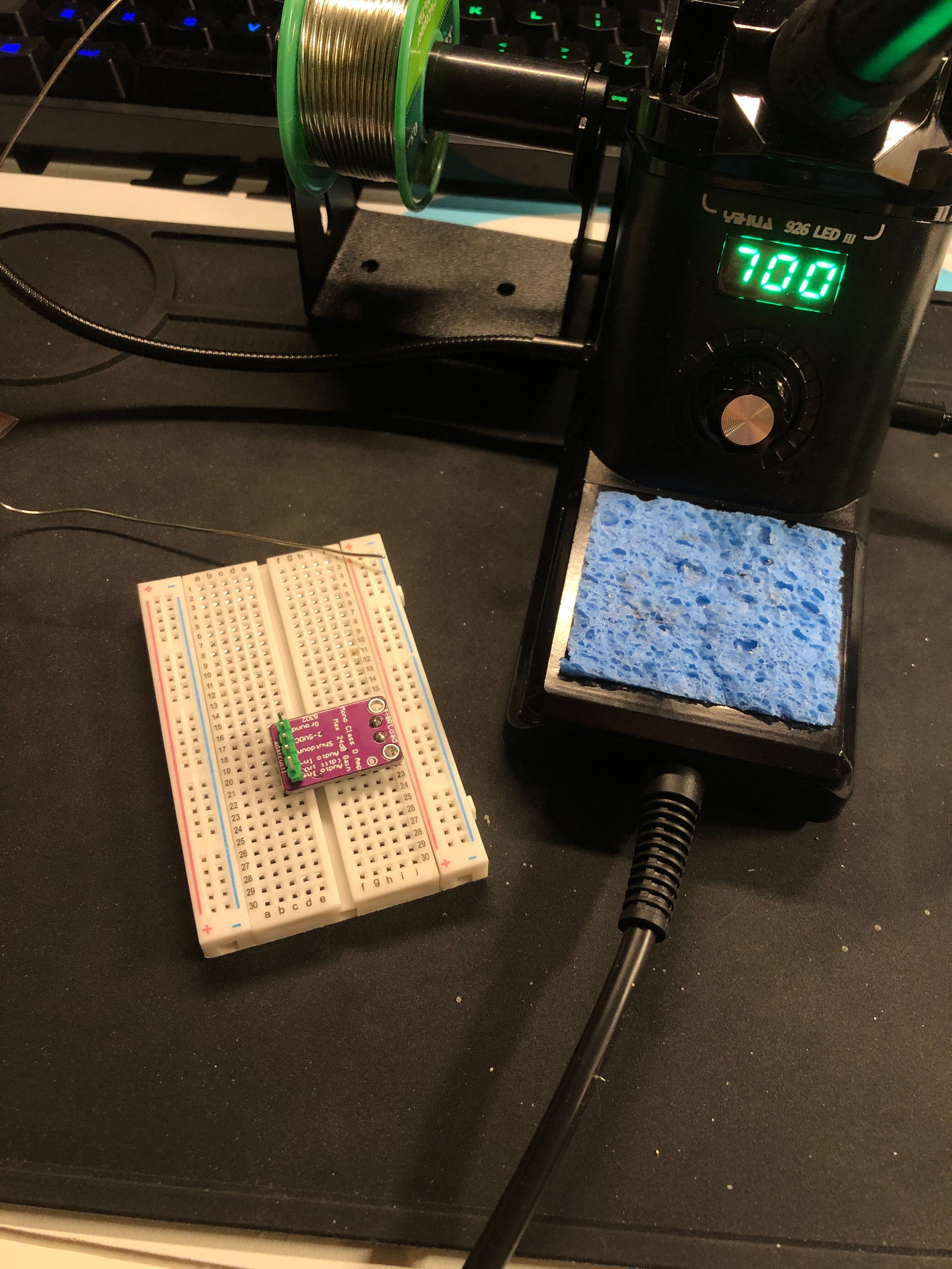
Soldering
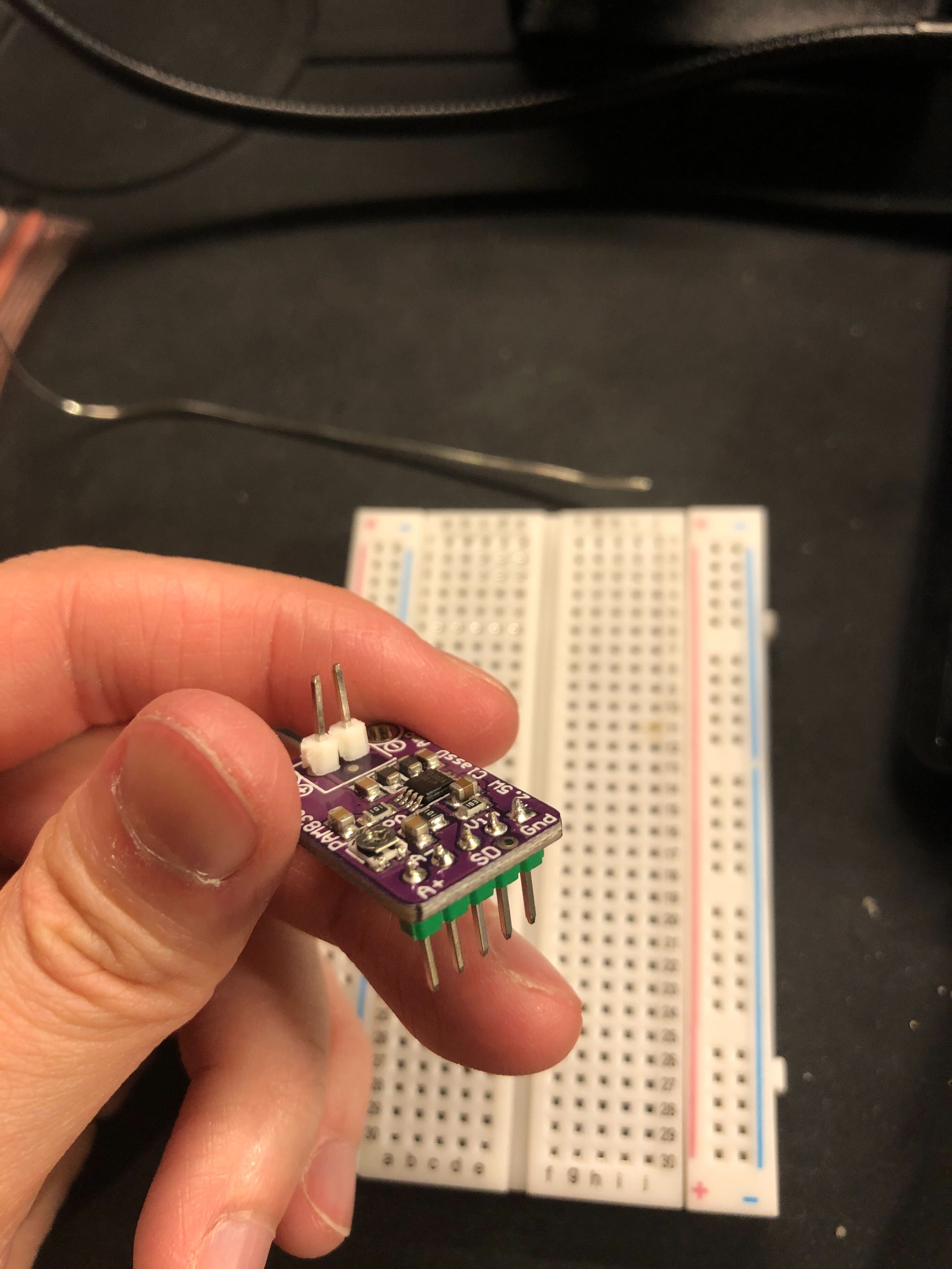
One of the great learning I have from this project is I learned how to do soldering. Thanks to the Youtube tutorials. The soldering station I used is from Amazon. These 2 image shows the result of soldering a pin header to an audio amplifier PAM8302. I didn’t end up using it. But you do need to know how to solder unless you are buying a pre-soldered BME280.
| Setup | Result |
|---|---|
 |
 |
Programming
IDE
I used VS Code with PlatformIO IDE following this tutorial. From my own experience, I think for beginners who have experience in programming, this approach is easier compared to Arduino IDE.
Features
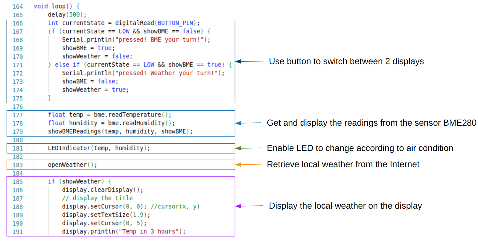 As the image shown above, in this project we have
- A button to switch the readings from the BME280 sensor and the local weather from the Internet.
- Room temperature and humidity from the BME280 sensor.
- LED indicators to show the air condition.
- Under the
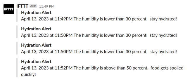
LEDIndicatorfunction we have IFTTT setup to send hydration alert to slack channel when the red LED is light up. - Using OpenWeather API to retrive local weather
Code
The code is open source and can the github repo can be found here. The project is written in C++ and the code is clean and commented, hope it helps!
Potential problems
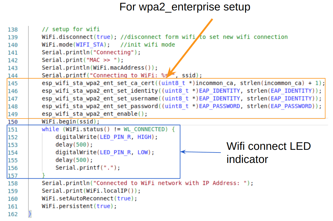
- WPA2 Enterprise
- Most of the tutorials online shows how to connect to home wifi, which only requires 3 lines of code:
1
2
3
4
5
// Replace with your network credentials
const char* ssid     = "REPLACE_WITH_YOUR_SSID";
const char* password = "REPLACE_WITH_YOUR_PASSWORD";
...
WiFi.begin(ssid, password);
- However, the university wifi (I’m using University of Michigan’s on-campus WiFi) has different setup. Luckily I found a github repo about how to connect, but there was another problem that, there will be compile errors from this line of code:
1
2
3
error: 'esp_wpa2_config_t' was not declared in this scope
 esp_wpa2_config_t wpa2_config = WPA2_CONFIG_INIT_DEFAULT();
 ^~~~~~~~~~~~~~~~~
This is because the code is outdated. From this issue case I found that the solution is in this commit.
- This is the wifi setup this project using:
- Most of the tutorials online shows how to connect to home wifi, which only requires 3 lines of code: