Resistive Sensors
Measuring Temperature
Thermistor: a temperature-dependent resistor, changing resistance with changes in temperature. Since for some materials, resistance is a function of temperature, we have:
\[R = f(T) \rightarrow T=f^{-1}(R)\]- To compute T, usually there is a graph we could look up.
- They are very sensitive and react to very small changes in temperature. They are best used when a specific temperature needs to be maintained, and when monitoring temperatures within 50°C of ambient.
Thermocouple: a temperature sensor that uses two different materials and measures voltage across two materials to measure temperature difference between hot and cold regions. It gives relative measurements.
\[\Delta V=\alpha \Delta T\]- Change in voltage gives the change in temp, where $\alpha$ is material property, a constant.
- One of the most commonly used sensor for temperature.
- Thermocouple Explained
Using both thermistor and thermocouple we will be able to measure the absolute temperature, since the thermistor can reflect its own temperature and the thermocouple can reflect the relatvie temperature.
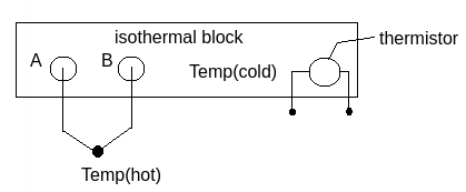
Here in the image, we use thermistor to measure the block’s temperature we call it Temp(cold). Then we have two material stick out of the block to measure the temperature we are investing and we call it Temp(hot) here. The thermocouple will give the relatvie temperature $\Delta T$ and the thermistor will give $T_0$, and we can derive absolute temperature from them.
Measuring Force
\[R=\rho \frac{L}{A} \qquad (1)\]How to measure force? You cannot directly measure the force but you can calculate it.
- R - Resistance, L - Length, A - Area, $\rho$ - Resistivity (Electrical constant)
- $\sigma$ is stress
- $\varepsilon$ is strain
- E is called young’s modulus which is a property of the material that tells us how easily it can stretch and deform.
To calculate change in resistance, based on equation(1) we have $ dR = \frac{dR}{dL}dL-\frac{dR}{dA}dA+\frac{dR}{d\rho}d\rho $ , then:
\[dR = \frac{\rho}{A}dL-\frac{\rho L}{A^2}dA+\frac{L}{A}d\rho\]Note that for most of the cases, the resistivity term could be neglected.
Then divided by R:
- Note there that the L is the original length and R is the original resistance.
- where $\frac{dL}{L}$ is longitudinal strain $\varepsilon_L$
- For $\frac{dA}{A}$ we need to account for radial strain $\varepsilon_r$, which needs Poisson’s ratio $\nu$.
- What is Poisson’s ratio? - It is a measure of the Poisson effect, the deformation (expansion or contraction) of a material in directions perpendicular to the specific direction of loading.
Plug $\frac{dA}{A}=-2\nu\varepsilon_L$ into equation(2) we have:
\[\frac{dR}{R}=(1+2\nu)\varepsilon_L+\frac{d\rho}{\rho}\]- Since we have a constant in the equation, we could have $\frac{\Delta R}{R}=G \varepsilon_L + \frac{d\rho}{\rho}$ where G is called “gage factor” which is a material property.
Such result, namely the change in resistance has linear relation with the strain, is used in products such as strain gage.
A load cell converts a force such as tension, compression, pressure, or torque into an electrical signal that can be measured and standardized. A strain gage is a sensor whose measured electrical resistance varies with changes in strain.
What is the difference between load cell and strain gage? - A strain gage is a single transducer used to convert the mechanical deformation into readable electrical output. Whereas, a load cell comprises an array of strain gages that convert the mechanical load into readable units.
EX: Load Cells
\(\sigma = \frac{F}{A} \qquad \varepsilon = \frac{F}{AE}\)
- $\sigma$ is stress, $\varepsilon$ is strain, E is young’s modulus
Then we have:
\[\frac{\Delta R}{R}=G \cdot \varepsilon = G \cdot \frac{F}{AE}\]How to relate force F to the change in resistance? Combine formulas we have above:
\[F = \frac{AE}{G}(\frac{\Delta R}{R})\]EX: Cantilever
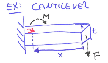
The force (F) is being applied which generates a moment (M) there.
- moment of inertia of a rectangle: $I = \frac{bt^3}{12}$
- distance to beam center: $c = \frac{t}{2}$
Then we have stress $\sigma$:
\[\sigma = \frac{M \cdot c}{I}=\frac{F\cdot x \cdot c}{I}\]Substitute inertia I we have:
\[\sigma = \frac{M t}{2 \frac{bt^3}{12}}=\frac{6M}{bt^2}=\frac{6Fx}{bt^2}\]Since $\varepsilon=\frac{\sigma}{E}$:
\[\varepsilon = \frac{6Fx}{Ebt^2}\]=>
\[\frac{\Delta R}{R}=G \cdot \varepsilon = G\frac{6Fx}{Ebt^2}\]where G is gage factor, $G=(1+2\nu) $ where $\nu$ is Poisson’s ratio.
Note:
- Meauring $\frac{\Delta R}{R}$ we can get any variable on the RHS
- This is how we build a moment sensor
Measuring Resistance
\[R = \frac{V}{I}\]We use changes in resistance to measure temperature and force. However, we cannot directly measure the resistance R, but we can measure voltage.
Option #1 Constant known current source
If we know the exact voltage and current, we can always calculate the resistance based on Rx = V/i.
Option #2 Unknown current
However, since the sensor’s resistance is changing, the current of the circuit will change as well. Thus, we have two unknown variables R and i, but only one equation Rx = V/i.
Voltage Divider: To solve this, we can use a math trick - transact resistance into measuring voltage by putting 2 resistors into series.
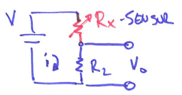
Since current is constant everywhere, $V = iR = i(R_x+R_2) \rightarrow i = \frac{V}{R_x+R_2}$ where $R_x$ is the sensor and $R_2$ is the regular resistor. We can also calculate $V_0=iR_2=V\cdot \frac{R_2}{(R_x+R_2)}$.
From equation above, we can solve for $R_x = \frac{R_2(V-V_0)}{V_0}$ by measuring $V_0$. Usually $R_2, R_x$ are matched at equilibrium. $(R_2 \approx R_x)$
Option #3 Wheatstone bridge
However, when sensors getting noisy, we want to create linearity. We can upgrade to Wheatstone Bridge. It is basically 2 voltage dividers.
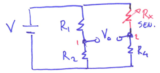
- Measuring $V_0$ to get $R_x$ with known $R_1, R_2, R_4$
Then, WHY is a wheatstone bridge better than a voltage divider?
- Because when the $\Delta R$ is too small, $R_x \approx R_2 \rightarrow V_2 \approx \frac{1}{2} V$, we will always have an offset at 1/2 V even when the resistance doesn’t change. We want V0 to be at 0 namely with no offset at equilibrium because in a practical way, we want to see that, say, when the strain gage is pressed the value goes down, and when the gage is strained, the value goes up. Also because the relation is not linear, which could cause problem when the sensors getting noisy.
Single point wheatstone bridge
Making all the resistor’s resistance matched the sensor’s resistance in equilibrium $R_1=R_2=R_3=R_x$. Then, we could have
\[V_0 = V \cdot(\frac{R}{R+R}-\frac{R}{R_x+R}) = V \cdot(\frac{1}{2}-\frac{R}{R_x+R})\]- When the sensor is unstrained, we would have reading 0. The relation is still non-linear but we get rid of offset.
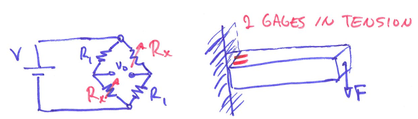
Half bridge
By adding one more sensor, namely replacing one of the resistors to be strain gage, this puts out twice of the voltage V0, and we can twice the sensitivity as one point bridge.
Proof
We know that for Wheatstone bridge circuit, we have the formula:
\[V_G = V\cdot (\frac{R_1}{R_1+R_2}-\frac{R_3}{R_3+R_4})\]For the quarter bridge case, use Rx to represent sensor we have:
\[V_{quarter} = V\cdot (\frac{R}{R+R}-\frac{R_x}{R_x+R}) = V\cdot (\frac{1}{2}-\frac{R_x}{R_x+R}) = V\cdot\frac{R-R_x}{2(R_x+R)}\]For the half bridge case, use Rx to represent sensor we have:
\[V_{half} = V\cdot (\frac{R}{R+R_x}-\frac{R_x}{R_x+R}) = V\cdot\frac{R-R_x}{R_x+R}\]Based on the equations above, we can tell that $V_{half} = 2 V_{quarter}$, half bridge has twice output of the quarter bridge.
Full bridge
To further improve the measurement, we could replace all the resistors to be strain gage and place them as the image shown below. Two on the top surface and two on the bottom surface.
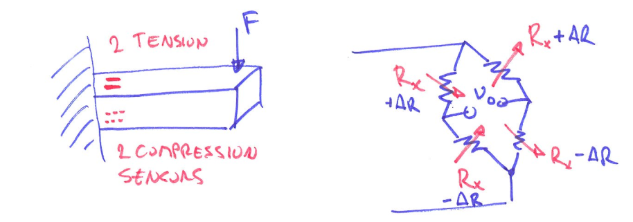
Now with full bridge, we have linearity and even higher sensitivity. But it costs more expense in labor and money.
This post is my notes from the class I am taking “CEE 575 Infrastructure Sensing” offered by Prof. Branko Kerkez at University of Michigan.