From Physics to Signals: How Sensors Work
Table of Contents
- Resistive Sensors (January 22, 2023)
- Capacitive Sensors (February 7, 2023)
- Inductive Sensors (February 19, 2023)
- Piezoelectric Sensors (February 20, 2023)
Resistive Sensors (January 22, 2023)
Measuring Temperature
Thermistor: a temperature-dependent resistor, changing resistance with changes in temperature. Since for some materials, resistance is a function of temperature, we have:
\[R = f(T) \rightarrow T=f^{-1}(R)\]- To compute T, usually there is a graph we could look up.
- They are very sensitive and react to very small changes in temperature. They are best used when a specific temperature needs to be maintained, and when monitoring temperatures within 50°C of ambient.
Thermocouple: a temperature sensor that uses two different materials and measures voltage across two materials to measure temperature difference between hot and cold regions. It gives relative measurements.
\[\Delta V=\alpha \Delta T\]- Change in voltage gives the change in temp, where $\alpha$ is material property, a constant.
- One of the most commonly used sensor for temperature.
- Thermocouple Explained
Using both thermistor and thermocouple we will be able to measure the absolute temperature, since the thermistor can reflect its own temperature and the thermocouple can reflect the relatvie temperature.
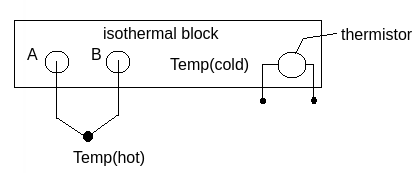
Here in the image, we use thermistor to measure the block’s temperature we call it Temp(cold). Then we have two material stick out of the block to measure the temperature we are investing and we call it Temp(hot) here. The thermocouple will give the relatvie temperature $\Delta T$ and the thermistor will give $T_0$, and we can derive absolute temperature from them.
Measuring Force
\[R=\rho \frac{L}{A} \qquad (1)\]How to measure force? You cannot directly measure the force but you can calculate it.
- R - Resistance, L - Length, A - Area, $\rho$ - Resistivity (Electrical constant)
- $\sigma$ is stress
- $\varepsilon$ is strain
- E is called young’s modulus which is a property of the material that tells us how easily it can stretch and deform.
To calculate change in resistance, based on equation(1) we have $ dR = \frac{\partial R}{\partial L}dL+\frac{\partial R}{\partial A}dA+\frac{\partial R}{\partial \rho}d\rho $ , then:
\[dR = \frac{\rho}{A}dL-\frac{\rho L}{A^2}dA+\frac{L}{A}d\rho\]Note that for most of the cases, the resistivity term could be neglected.
Then divided by R:
- Note there that the L is the original length and R is the original resistance.
- where $\frac{dL}{L}$ is longitudinal strain $\varepsilon_L$
- For $\frac{dA}{A}$ we need to account for radial strain $\varepsilon_r$, which needs Poisson’s ratio $\nu$.
- What is Poisson’s ratio? - It is a measure of the Poisson effect, the deformation (expansion or contraction) of a material in directions perpendicular to the specific direction of loading.
Plug $\frac{dA}{A}=-2\nu\varepsilon_L$ into equation(2) we have:
\[\frac{dR}{R}=(1+2\nu)\varepsilon_L+\frac{d\rho}{\rho}\]- Since we have a constant in the equation, we could have $\frac{\Delta R}{R}=G \varepsilon_L$ where G is called “gage factor” which is a material property.
Such result, namely the change in resistance has linear relation with the strain, is used in products such as strain gage.
A load cell converts a force such as tension, compression, pressure, or torque into an electrical signal that can be measured and standardized. A strain gage is a sensor whose measured electrical resistance varies with changes in strain.
What is the difference between load cell and strain gage? - A strain gage is a single transducer used to convert the mechanical deformation into readable electrical output. Whereas, a load cell comprises an array of strain gages that convert the mechanical load into readable units.
EX: Load Cells
\(\sigma = \frac{F}{A} \qquad \varepsilon = \frac{F}{AE}\)
- $\sigma$ is stress, $\varepsilon$ is strain, E is young’s modulus
Then we have:
\[\frac{\Delta R}{R}=G \cdot \varepsilon = G \cdot \frac{F}{AE}\]How to relate force F to the change in resistance? Combine formulas we have above:
\[F = \frac{AE}{G}(\frac{\Delta R}{R})\]EX: Cantilever
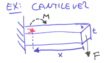
The force (F) is being applied which generates a moment (M) there.
- moment of inertia of a rectangle: $I = \frac{bt^3}{12}$
- distance to beam center: $c = \frac{t}{2}$
Then we have stress $\sigma$:
\[\sigma = \frac{M \cdot c}{I}=\frac{F\cdot x \cdot c}{I}\]Substitute inertia I we have:
\[\sigma = \frac{M t}{2 \frac{bt^3}{12}}=\frac{6M}{bt^2}=\frac{6Fx}{bt^2}\]Since $\varepsilon=\frac{\sigma}{E}$:
\[\varepsilon = \frac{6Fx}{Ebt^2}\]=>
\[\frac{\Delta R}{R}=G \cdot \varepsilon = G\frac{6Fx}{Ebt^2}\]where G is gage factor, $G\approx(1+2\nu)$ when the change in resistivity is negligible, where $\nu$ is Poisson’s ratio.
Note:
- Meauring $\frac{\Delta R}{R}$ we can get any variable on the RHS
- This is how we build a moment sensor
Measuring Resistance
\[R = \frac{V}{I}\]We use changes in resistance to measure temperature and force. However, we cannot directly measure the resistance R, but we can measure voltage.
Option #1 Constant known current source
If we know the exact voltage and current, we can always calculate the resistance based on Rx = V/i.
Option #2 Unknown current
However, since the sensor’s resistance is changing, the current of the circuit will change as well. Thus, we have two unknown variables R and i, but only one equation Rx = V/i.
Voltage Divider: To solve this, we can use a math trick - transact resistance into measuring voltage by putting 2 resistors into series.
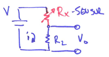
Since current is constant everywhere, $V = iR = i(R_x+R_2) \rightarrow i = \frac{V}{R_x+R_2}$ where $R_x$ is the sensor and $R_2$ is the regular resistor. We can also calculate $V_0=iR_2=V\cdot \frac{R_2}{(R_x+R_2)}$.
From equation above, we can solve for $R_x = \frac{R_2(V-V_0)}{V_0}$ by measuring $V_0$. Usually $R_2, R_x$ are matched at equilibrium. $(R_2 \approx R_x)$
Option #3 Wheatstone bridge
However, when sensors getting noisy, we want to create linearity. We can upgrade to Wheatstone Bridge. It is basically 2 voltage dividers.
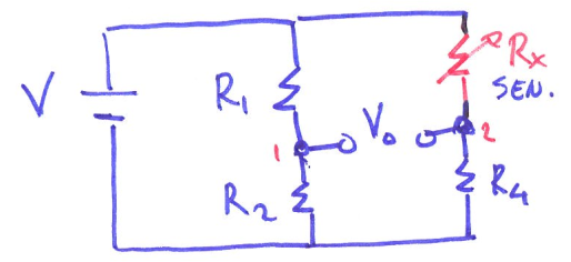
- Measuring $V_0$ to get $R_x$ with known $R_1, R_2, R_4$
Then, WHY is a wheatstone bridge better than a voltage divider?
- Because when the $\Delta R$ is too small, $R_x \approx R_2 \rightarrow V_2 \approx \frac{1}{2} V$, we will always have an offset at 1/2 V even when the resistance doesn’t change. We want V0 to be at 0 namely with no offset at equilibrium because in a practical way, we want to see that, say, when the strain gage is pressed the value goes down, and when the gage is strained, the value goes up. Also because the relation is not linear, which could cause problem when the sensors getting noisy.
Single point wheatstone bridge
Making all the resistor’s resistance matched the sensor’s resistance in equilibrium $R_1=R_2=R_3=R_x$. Then, we could have
\[V_0 = V \cdot(\frac{R}{R+R}-\frac{R}{R_x+R}) = V \cdot(\frac{1}{2}-\frac{R}{R_x+R})\]- When the sensor is unstrained, we would have reading 0. The relation is still non-linear but we get rid of offset.
Half bridge
By adding one more sensor, namely replacing one of the resistors to be strain gage, this puts out twice of the voltage V0, and we can twice the sensitivity as one point bridge.
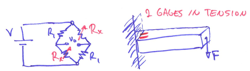
Proof
We know that for Wheatstone bridge circuit, we have the formula:
\[V_G = V\cdot (\frac{R_1}{R_1+R_2}-\frac{R_3}{R_3+R_4})\]For the quarter bridge case, use Rx to represent sensor we have:
\[V_{quarter} = V\cdot (\frac{R}{R+R}-\frac{R_x}{R_x+R}) = V\cdot (\frac{1}{2}-\frac{R_x}{R_x+R}) = V\cdot\frac{R-R_x}{2(R_x+R)}\]For the half bridge case, use Rx to represent sensor we have:
\[V_{half} = V\cdot (\frac{R}{R+R_x}-\frac{R_x}{R_x+R}) = V\cdot\frac{R-R_x}{R_x+R}\]Based on the equations above, we can tell that $V_{half} = 2 V_{quarter}$, half bridge has twice output of the quarter bridge.
Full bridge
To further improve the measurement, we could replace all the resistors to be strain gage and place them as the image shown below. Two on the top surface and two on the bottom surface.
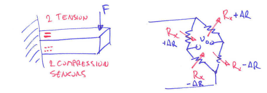
Now with full bridge, we have linearity and even higher sensitivity. But it costs more expense in labor and money.
Capacitive Sensors (February 7, 2023)
Capacitor
Capacitor is a circuit element that stores charges, sometimes called “charge buckets.”
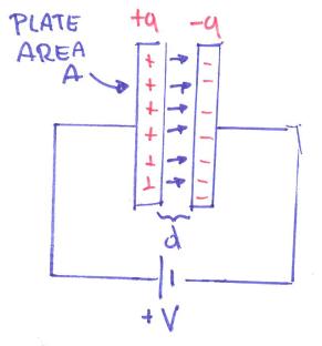
As shown in the image, each plate receives an equal but opposite amount of charge. At a fixed voltage, the amount of the charge is proportional to the area A and inversely proportional to the distance d. When the area gets larger, or the distance gets closer, the amount of charges increase.
- where q is number of charges, V is voltage, and C is capacitance with unit
coulomb/volt=farad.
Dielectric constant: When filling the space between plates with non-conductive material, we have a new capacitance $C_{new}=k\cdot C_{vacuum}$ where k is the dielectric constant, it is a material property.
The capacitance of a capacitor is given by:
\[C=\frac{k \cdot \varepsilon_0 \cdot A}{d}\]- where $\varepsilon_0 \approx 8.85\times 10^{-12}\ \mathrm{F/m}$ is the permittivity of vacuum, k is a dielectric constant of the material in between.
Capacitive sensor
Definition: A capacitive sensor converts changes in position, geometry or properties of a dielectric into electric signals.
\(C = f(A, d, k)\) where A is area, d is distance, k is dielectric property (the thing in between the two plates)
Accelerometer
Force - displacement
- Displacement is a direct indicator of movement
- Displacement is indirect indicator of other variables such as force/pressure. In other words, if you can measure displacement, you can measure force.
Lateral movement
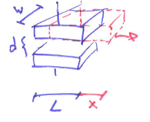
- C = f(A, d, k)
- Motion of top plate causes linear change in capacitance.
- From $C_0=\frac{k\varepsilon_0 A}{d}$ to $C=\frac{k\varepsilon_0 W(L-x)}{d}$
- However, we have to guarantee that lateral motion does not affect the separation between plates, such design is not good for small displacements and hard to implement.
Plate separation
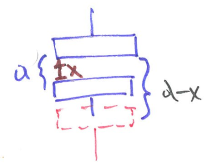
- C = f(A, d, k)
- Most sensors are based on a change in the plate separation d.
- From $C_0=\frac{k\varepsilon_0 A}{d}$ to $C=\frac{k\varepsilon_0 A}{d-x}$
- -x or +x is about how you define the reference, here we have the sensor moving downward
- The change is non-linear, but for small changes x we can approximate through the use of taylor series. Then for the capacitance we can get: $C \approx \frac{k\varepsilon_0 A}{d}[1+\frac{x}{d}+\frac{x^2}{d^2}]$
- For $x \ll d$ the change in C is linear with change in displacement x.
- The non-linearity appears in the higher order terms: $\frac{x^2}{d^2}$, etc., and could be a concern if we want high accuracy for displacement.
Improvement: differential displacements
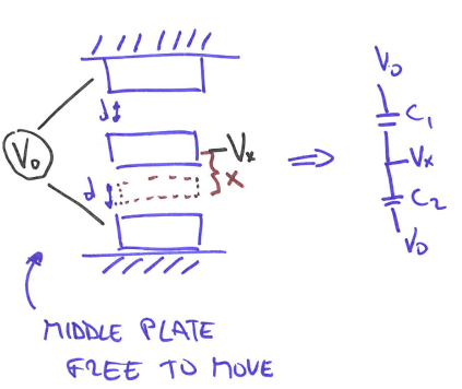
- We change the design to 2 fixed plates and the middle plate is free to move.
If we are able to measure $\Delta C=C_2-C_1$, then:
\[\Delta C\approx\frac{k\varepsilon_0 A}{d}[1+\frac{x}{d}+\frac{x^2}{d^2}]-\frac{k\varepsilon_0 A}{d}[1-\frac{x}{d}+\frac{x^2}{d^2}]=\frac{k\varepsilon_0 A}{d}\frac{2x}{d}\]- The second-order non-linearity is subtracted away, but higher odd-order terms remain, and this design is good for accuracy purpose.
- However, how do we measure $\Delta C$, how do we subtract one capacitor from another?
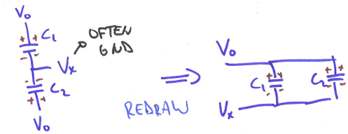
- The circuit above has two capacitors in parallel. When connect to the power, the change of the total capacitance would be $\Delta C = C_1+C_2$, which is not subtraction we are looking for.
Solution #1 opposing D.C. voltage
DC stands for direct current. In direct current, the current flows in one direction, but its magnitude need not be constant.
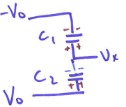
- Charges cancel -> $V_x =0 $ when plate does not move
- When middle plate moves -> $V_x$ changes sign depending on direction if the place move up or down. Now we have the subtraction we want.
- However, the voltages will saturate very quickly again after plate moves, such that it is hard to measure.
Solution #2 A.C. source
AC stands for alternating voltage. In alternating current, the voltage periodically changes from positive to negative and from negative to positive, and the direction of the current also periodically changes accordingly.
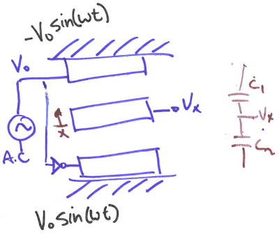
- Set $f \approx 1$MHz very FAST because we don’t want the capacitors to settle down.
- If middle plate is centered, then currents cancel -> $V_x=0$
- If plate move, charge buildup does not remain constant -> $V_x$ changes.
- Substitute $C=\frac{k \cdot \varepsilon_0 \cdot A}{d} $ to above equation based on change in d or A. For the example’s situation ($\Delta d$), we have the result:
- Note there that $V_0$ is alternating.
Spring mass damper system
Now we relate voltage changes with the displacement changes linearly, how do we build an accelerometer from it?
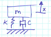
- A mass m is attached to a spring and a damper
- Hook’s law: spring force $F_s=-kx$, damping force $F_d=-c \frac{dx}{dt}=-c \dot{x}$
- k is spring constant, c is damping constant.
- Newton’s law: $F=ma$
- Put everything together we have:
Divide by m to get common form we have $\ddot{x}+ \frac{c}{m} \dot{x}+\frac{k}{m}x = 0$. Then let:
- natural frequency $\omega_0=\sqrt{\frac{k}{m}}$
- damping ratio = $\zeta=\frac{c}{2\sqrt{km}}$
Thus, we have
\[\ddot{x}+2\zeta \omega_0 \dot{x}+\omega_0^2x=0\]Now we can build something to measure acceleration. We hook the middle plate to a mass on a spring like in the image.
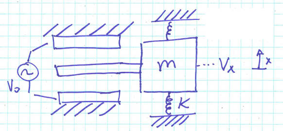
- For housing acceleration a and mass displacement x relative to the housing, $m\ddot{x}+c\dot{x}+kx=-ma$. Well below the natural frequency, $a\approx-\frac{kx}{m}=-\frac{kd}{m}\frac{V_x}{V_0}$, with both measured along the same axis.
- Now we have a relation between output voltage $V_x$ and the acceleration $a$. Meaning that we have built an accelerometer.
How to measure capacitance
We have explored how capacitance can be used to measure movement, but how do we measure capacitance?
Method #1 RC-based
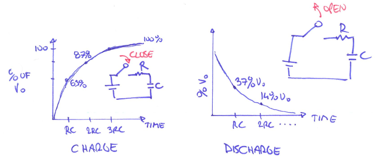
When a capacitor is placed in series with a resistor, we can get some useful relationships. It can be shown that the voltage across a capacitor in an RC (resistor+capacitor) circuit is given by:
\[V(t)=V_0(1-e^\frac{-t}{RC})\]- R is resistance, C is capacitance
- $\tau = R\cdot C$ where $\tau$ is a time constant. Measure $\tau$ can help to measure C
Method #2 Charge-based
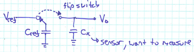
- Rely on the ability of capacitor to hold charge
- $C = \frac{Q}{V}$
Details:
- Charge $C_{ref} \rightarrow Q=C_{ref}\cdot V_{ref}$
- Flip the switch to the right, the charge Q would not change
- Flip left: $Q = C_{ref}\cdot V_{ref}$; Flip right: $Q=(C_{ref}+C_x)\cdot V_o$
- From the equations above, we have:
- Then we can get $C_x$ by measuring $V_o$ after flipping switch to the right.
- Note that this method may be prone to error because the actual switch can inject charge into the system.
Method #3 Series R-C bridge
Definition: Impedance is the opposition to alternating current presented by the combined effect of resistance and reactance in a circuit.
RC-Impedance
- A series RC circuit will offer the opposition to the current flow due to both the resistor and capacitor. Let, the alternating voltage of angular frequency $\omega$ is applied across the series RC combination. Then the formula of the impedance of RC circuit is $z = R+\frac{1}{j\omega C}$ or $z = R-\frac{j}{\omega C}$.
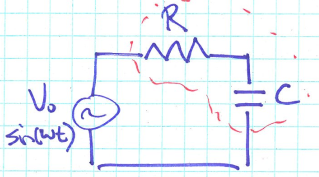
- $V = z \cdot i$
Measuring capacitance
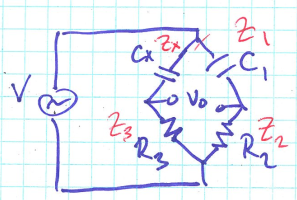
- Here we have a series R-C bridge
- When $V_0=0$ it can be shown that $z_1\cdot z_3=z_2\cdot z_x$
- Then substitute $z = R-\frac{j}{\omega C}$ into the equation above, we have
- Adjust $C_1$ until $V_0=0$ then we can calculate $C_x$ since we know $C_1, R_2, R_3$
Inductive Sensors (February 19, 2023)
Electromagnetic Induction
Electromagnetic induction: We know that a current flowing in a wire would produce a magnetic field. To increase the measurable effect of the field we can spin the wire into a coil.
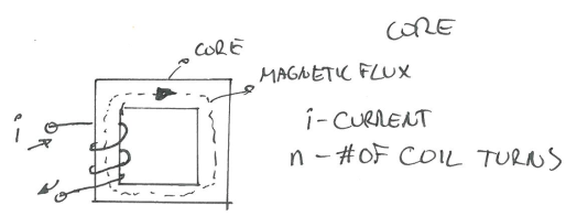
For one turn of the coil, the magnetic flux is:
\[\Phi=\frac{ni}{\mathcal{R}}\]- where $\mathcal{R}$ is the reluctance, a property of the core material. Magnetic reluctance is analogous to electrical resistance in an electrical circuit.
- $\mathcal{l}$ - total length of flux path
- A path which is followed by magnetic lines of force and in which the magnetic flux density is significant.
- $\mu_0$ - permeability of vacuum
- $\mu$ - relative permeability of core material
- A - cross sectional area of the coil
- where $\Phi$ is magnetic flux for one turn of the coil, unit Weber. And $\Psi$ is the flux linkage, unit Weber-turn.
Definition: The inductance L of a coil is the total flux per unit current:
\[L = \frac{\Psi}{i}=\frac{n^2}{\mathcal{R}}\]- The relationship between inductance and current is: change in current causes a measurable voltage.

Further, change in the magnetic field can induce a change in current and vice versa.
\[\frac{d\Psi}{dt} \propto \frac{di}{dt} \rightarrow V\propto \frac{d \Psi}{dt}\]Mutual Inductance
- An alternating current flow in one coil can induce a current flow in another coil.
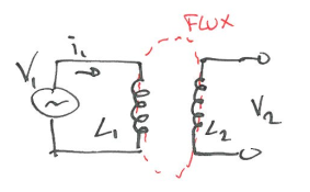
- where M is coefficient of mutual inductance.
- In general, it depends on the reluctance(distance and material between coils) with which a magnetic flux can flow between inductors.
- $i_1$ would induce another current flow $i_2$ in the RHS circuit
Usage
The Linear Variable Differential Transformer (LVDT)
Linear variable differential transformer is a type of electrical transformer used for measuring linear displacement (position).
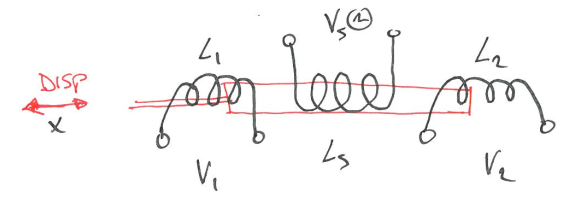
The red bar is the core moving in x direction, and Vs is the source power. According to effect of mutual inductance, we know $V_1 = -M_1\frac{di_s}{dt}$ and $V_2 = -M_2\frac{di_s}{dt}$. Red bar’s change $\Delta x$ in position will cause a change in $M_1$ and $M_2$ due to reluctance changes. Thus,
\[V_0 = V_1 - V_2 = (-M_1\frac{di_s}{dt}) - (-M_2\frac{di_s}{dt}) = (M_2 - M_1)\frac{di_s}{dt}\]Why we need 2 secondary coils here? - It gives the linearity, ($M_2-M_1$) can show it’s linear. With one coil, the change in M is non-linear.
How do we measure?
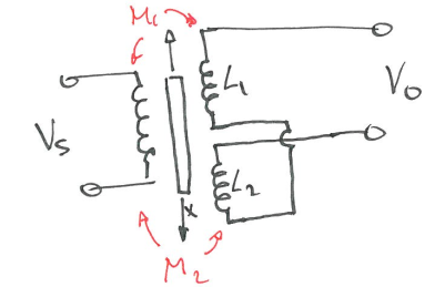
- At $x=0$, $V_0=0$, $M_1=M_2$
- Connect in open-wiring configuration
- As core moves, it will change $M_1, M_2$, this will change the induced voltages $V_1, V_2$, and the amplitude of $V_0$ is linear with $\Delta x$.
Electromagnetic Flow Meter
- Electromagnetic flow meters are comprised of a transmitter and sensor that together measure water flow.
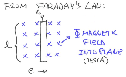
- If a conductor of length l(m) is moving perpendicular to a magnetic flux density $B$ at a velocity e (m/s), the voltage $V_o$ is induced:
- One might more familiar with the form $V = Blv$ but they are the same.
- With Faraday’s law, we can build flow meter from it.
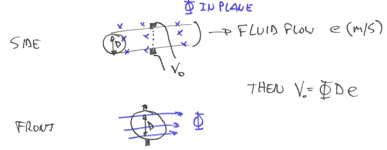
In the case of a flow meter, the conductor is the liquid. We know that
\[Q = A \cdot e \qquad A = \frac{\pi D^2}{4}\]- e is the velocity of the flow m/s
- A is the cross-sectional area of the pipe
- Q is the flow of the liquid $m^3/s$
- D is the diameter
- Measuring the voltage can help us to measure the flow, although it is very difficult to build flow meter.
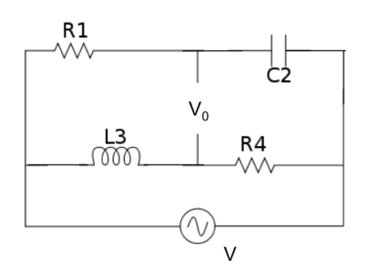
Inductive-loop traffic detectors (RLC circuit)
Vehicle detection loops can detect vehicles passing or arriving at a certain point. When no car is present, the inductance of the loop is a steady, known value. When a car passes over the loop, the inductance changes. We can simplify it to a circuit like in the figure below, which is a common tool for measuring the change of an unknown inductor.
Definition: Impedance is the opposition to alternating current presented by the combined effect of resistance and reactance in a circuit.
- Impedance for a pure resistor is its resistance
- Let the capacitance of a capacitor is C and the alternating current passing through the capacitor circuit have the angular frequency $\omega$. Then the impedance experiences by the current passing through the capacitor is $z = \frac{1}{j\omega C}$
- If L is the inductance of an inductor operating by an alternating voltage of angular frequency $\omega$, then the impedance offered by the pure inductor to the alternating current is, $z=j\omega L$.
- Source
To obtain the value $L_3$, a variable capacitor $C_2$ is digitally adjusted until the bridge circuit is balanced ($V_0 = 0$). Then, it can be shown that $z_1 \cdot z_4 = z_3 \cdot z_2 $. Thus,
$R_1\cdot R_4 = (j\omega L_3)(\frac{1}{j\omega C_2})$
$ L_3 = R_1\cdot R_4 \cdot C_2 $
Piezoelectric Sensors (February 20, 2023)
Piezoelectric Effect
Piezoelectric Effect is the ability of certain materials to generate an electric charge in response to applied mechanical stress. The word Piezoelectric is derived from the Greek piezein, which means to squeeze or press, and piezo, which is Greek for “push”.
- When subjected to a mechanical force, some crystalline materials become electrically polarized.
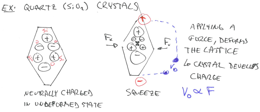
- Similarly, if we apply a voltage (charge) to the crystal, it will deform mechanically. - “Inverse” piezoelectric effect.
- Naturally occurring crystal materials have limitations when it comes to sensing: fragility, shape possibilities. (For example, before we squeeze the crystal enough to have measurable voltage, it might already broken.)
- We can, however, make our own metal oxide-based piezoelectric ceramics.
Piezoelectric Constant
The response of piezoelectric elements is highly directionally dependent (anisotropic): 1) direction of polarization 2) direction of applied force
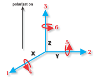
- This is the standard frame of reference
- All constants are given in: $\propto_{AB}$
- $\propto$ is constant, A is direction of polarization, B is direction of force
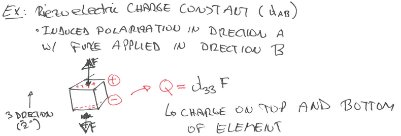
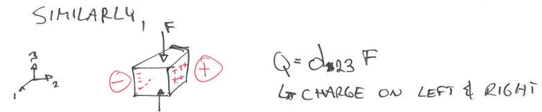
- $\propto$ is constant, A is direction of polarization, B is direction of force
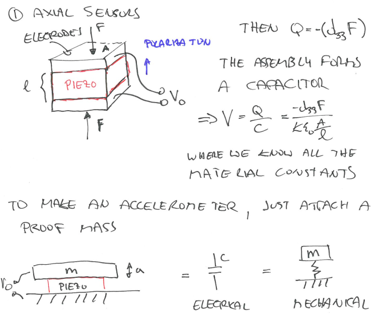
Piezoelectric sensors
There are 2 common types of piezoelectric sensors: 1) Axial 2) Flexural
This post is my notes from the class I am taking “CEE 575 Infrastructure Sensing” offered by Prof. Branko Kerkez at University of Michigan.