Machining, 3D Printing, Laser Cutting, Soldering, and Welding
Recently, I’ve been thinking that versatility is a very important skill for a robotics engineer in the age of AI. The University of Michigan has two places to learn manufacturing skills, from basic machining and 3D printing to CNC and welding, the training map is below. This post is where I keep track of what I’ve learned and built.
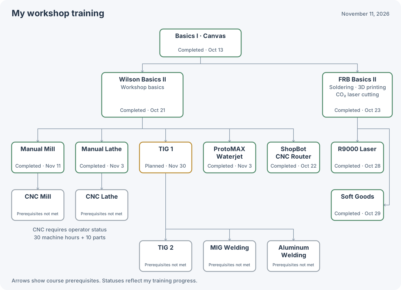
Table of Contents
- Workshop Basics
- Basic Workshop Safety I Completed
- Wilson Center Basics II Completed
- FRB Basics II - Soldering, CO2 Laser Cutting, 3D Printing Completed
- Introduction to Soft Goods Completed
- Machining
- Manual Mill Completed
- Manual Lathe Completed
- Digital Fabrication
- Universal R9000 Completed
- ProtoMAX Waterjet Completed
- ShopBot CNC Router Completed
- Welding
- TIG 1 Planned
- TIG 2 Prerequisites not met
- MIG Welding Prerequisites not met
- Aluminum Welding Prerequisites not met
Workshop Basics
Basic Workshop Safety I
Location: Canvas
Status: Completed · October 13, 2026
This is the starting point for all training sessions. It introduces basic workshop safety rules through Canvas modules and quizzes that must be passed.
Wilson Center Basics II
Location: Wilson Student Team Project Center
Status: Completed · October 21, 2026
This is the starting point for all hands-on training at the Wilson Center. It consists of two parts. The first is on Canvas, with videos and quizzes covering the basics and introducing the final project.
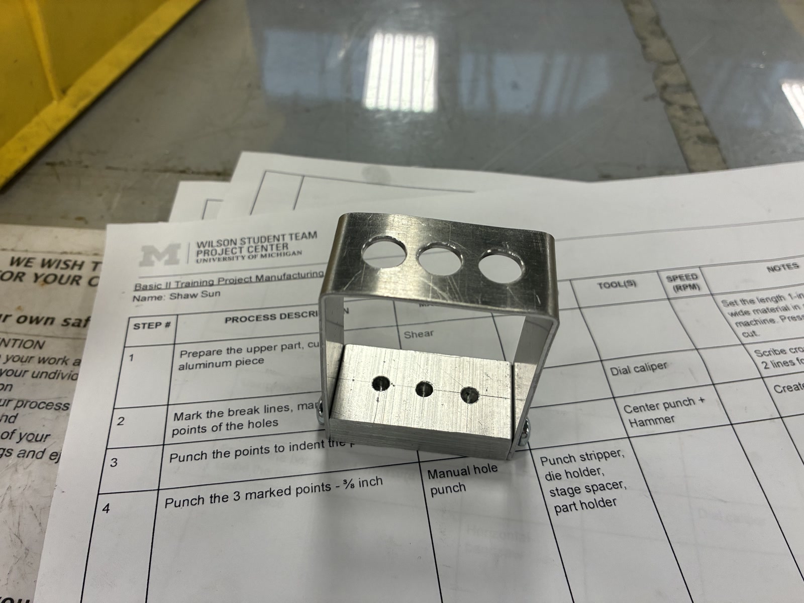
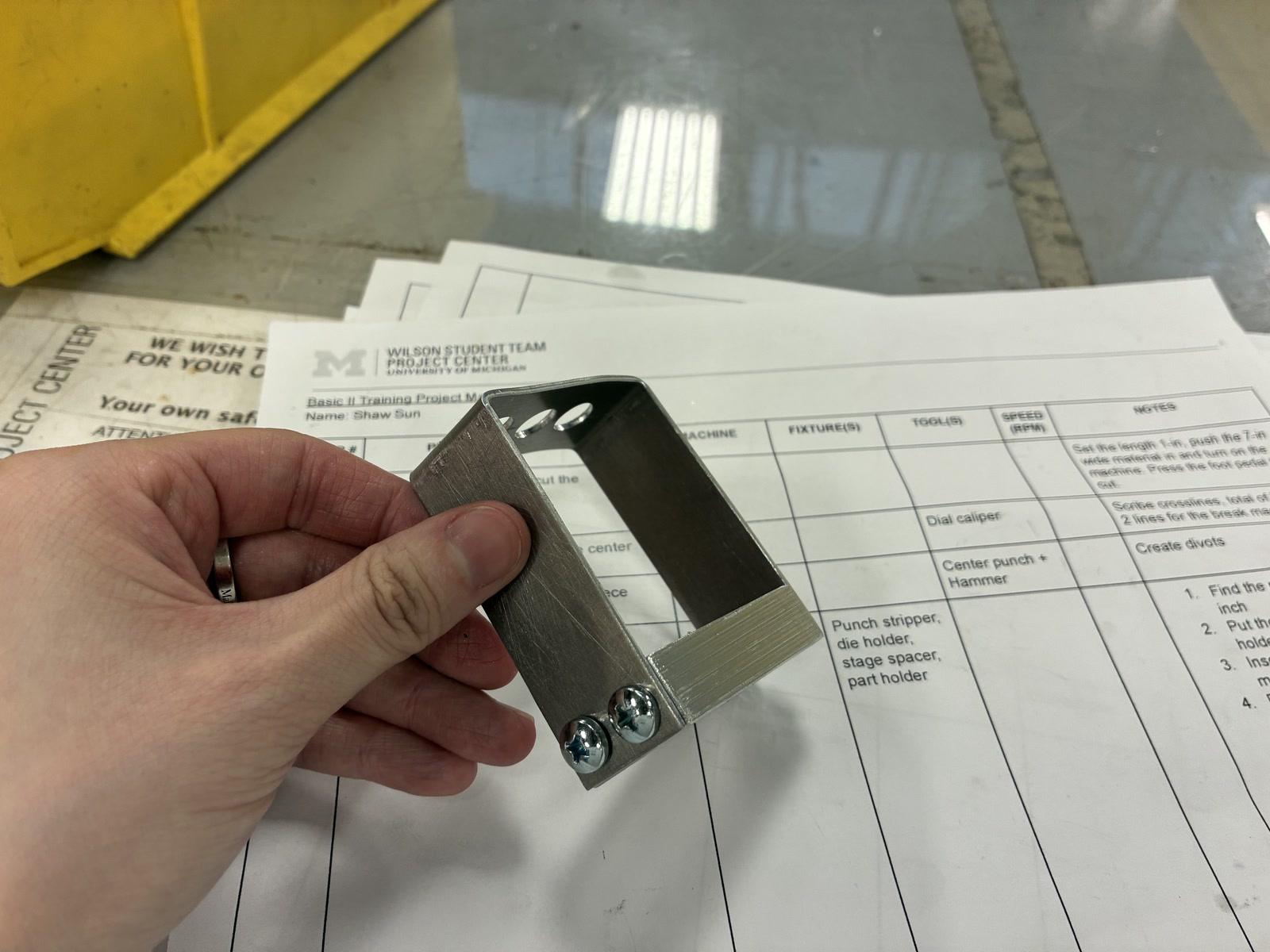
The second part is an in-person project. I made two aluminum pieces using the workshop tools below.
| Final Result - A pencil holder | |
|---|---|
 |
 |
| Photo | Tool and notes |
|---|---|
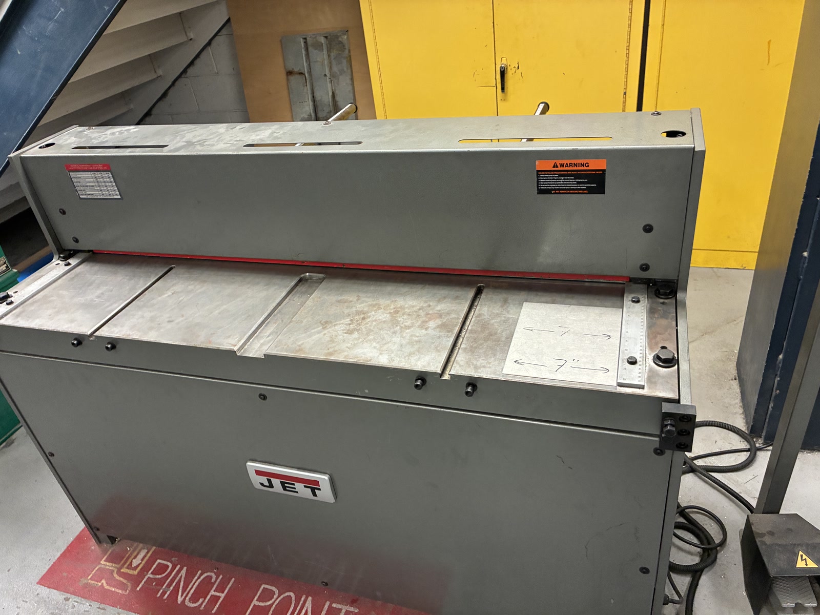 |
Shear. This machine was used to cut the sheet aluminum to size. |
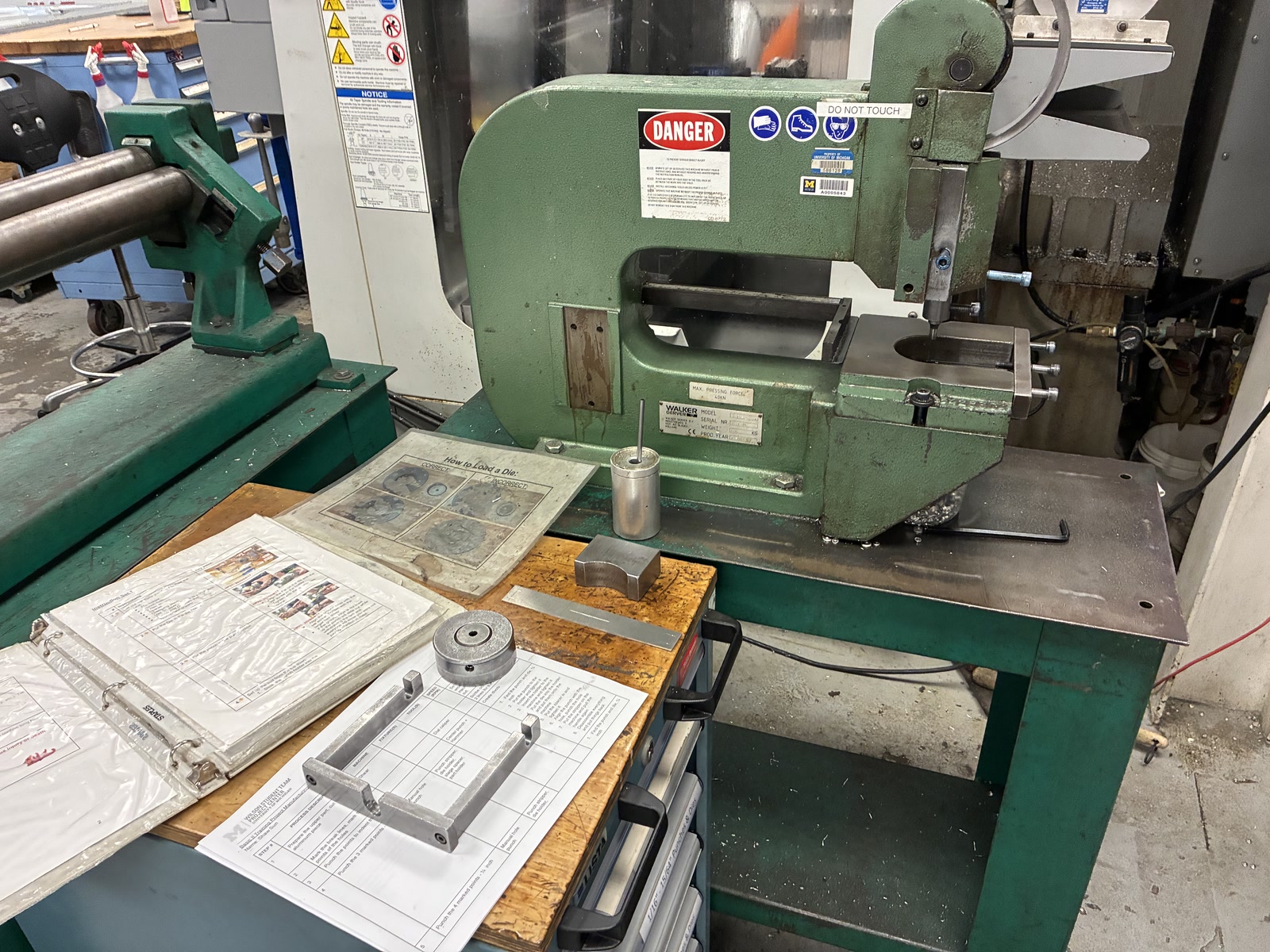 |
Manual hole punch. This machine was used to punch the holes in the sheet aluminum. |
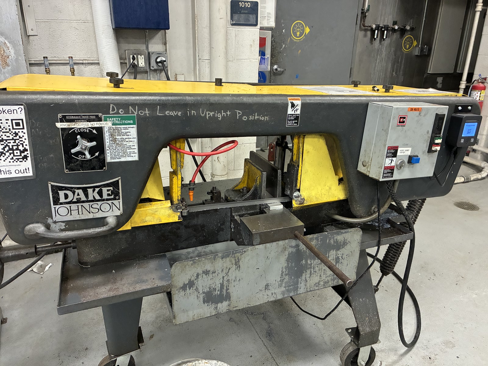 |
Horizontal bandsaw. This machine was used to cut the aluminum stock for the bottom piece. |
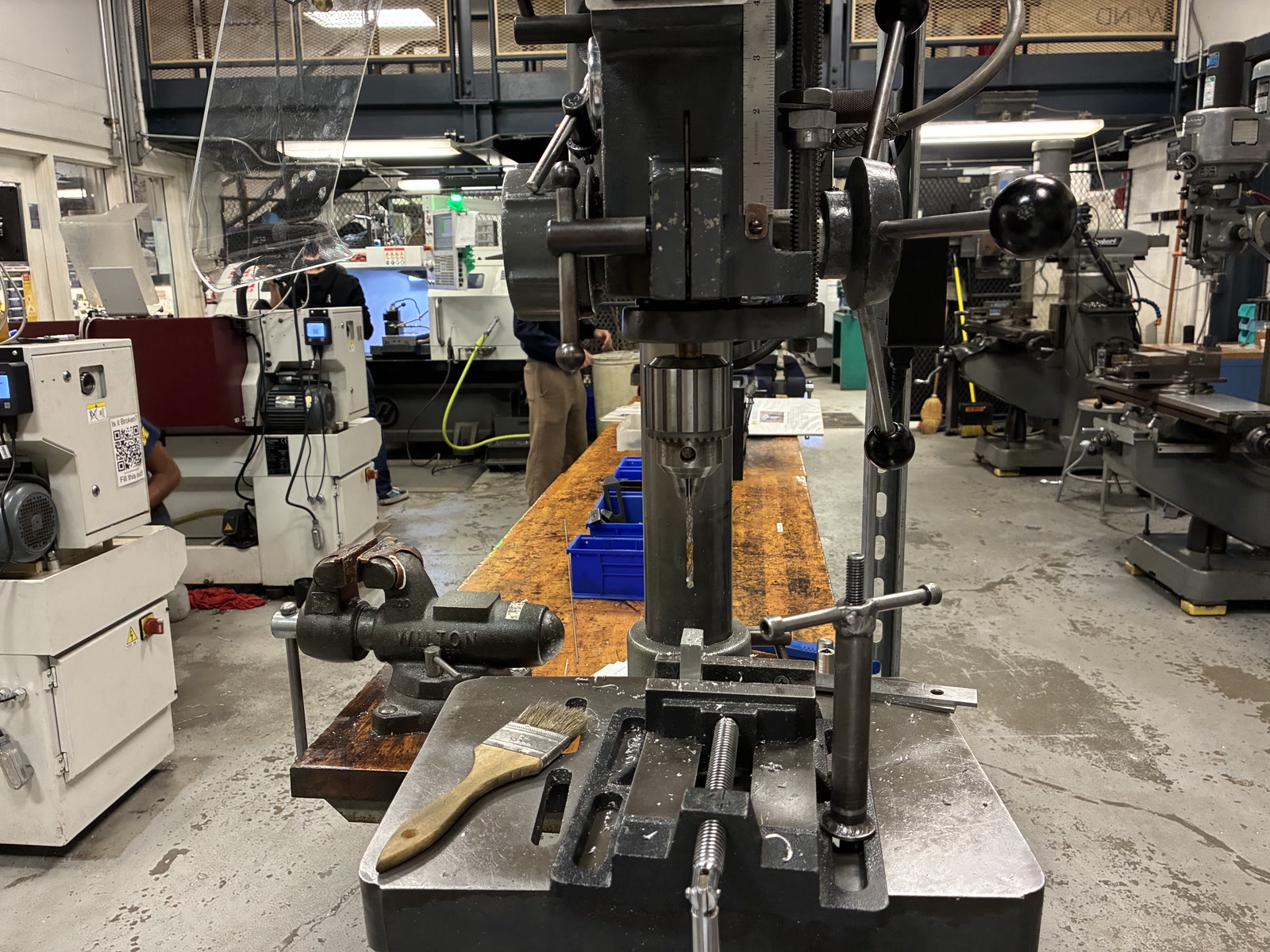 |
Drill press. This machine was used to drill the blind holes in the bottom piece. |
Dial calipers were used to measure the pieces and mark cut lines and hole locations. Files and deburring tools were used to smooth the edges and holes. A brake was used to bend the sheet aluminum, and a hand tap was used to cut internal threads in the bottom piece.
FRB Basics II - Soldering, CO2 Laser Cutting, 3D Printing
Location: Ford Robotics Building
Status: Completed · October 23, 2026
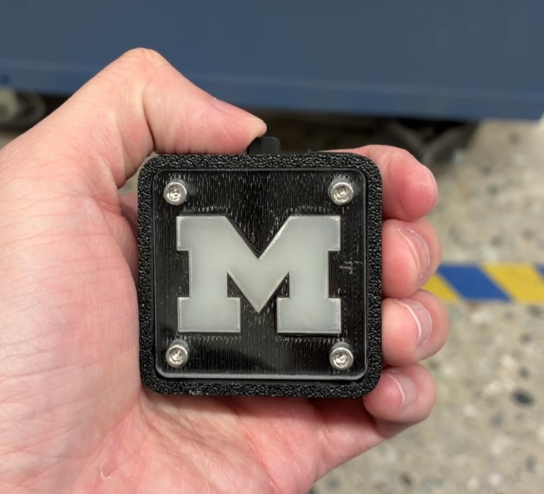
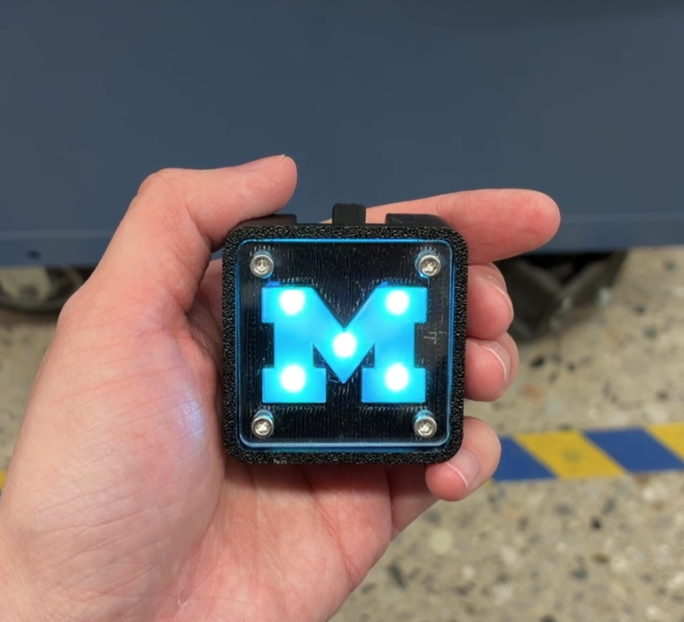
I built a small battery-powered light box with an engraved Michigan “M” on a clear acrylic panel.
| Finished Light Box | LEDs On |
|---|---|
 |
 |
Kit components
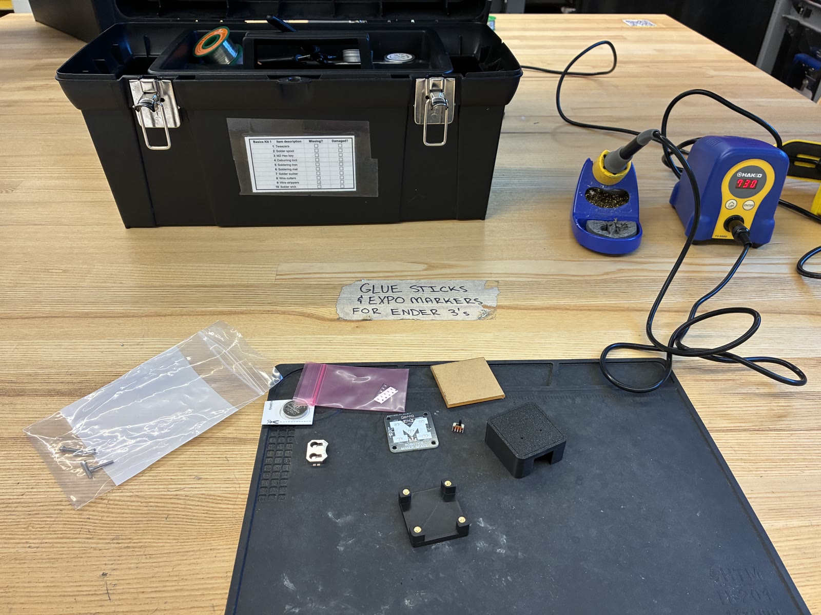
The kit included the designs, a preprinted enclosure, inserts, screws, and electronic components.
3D printing
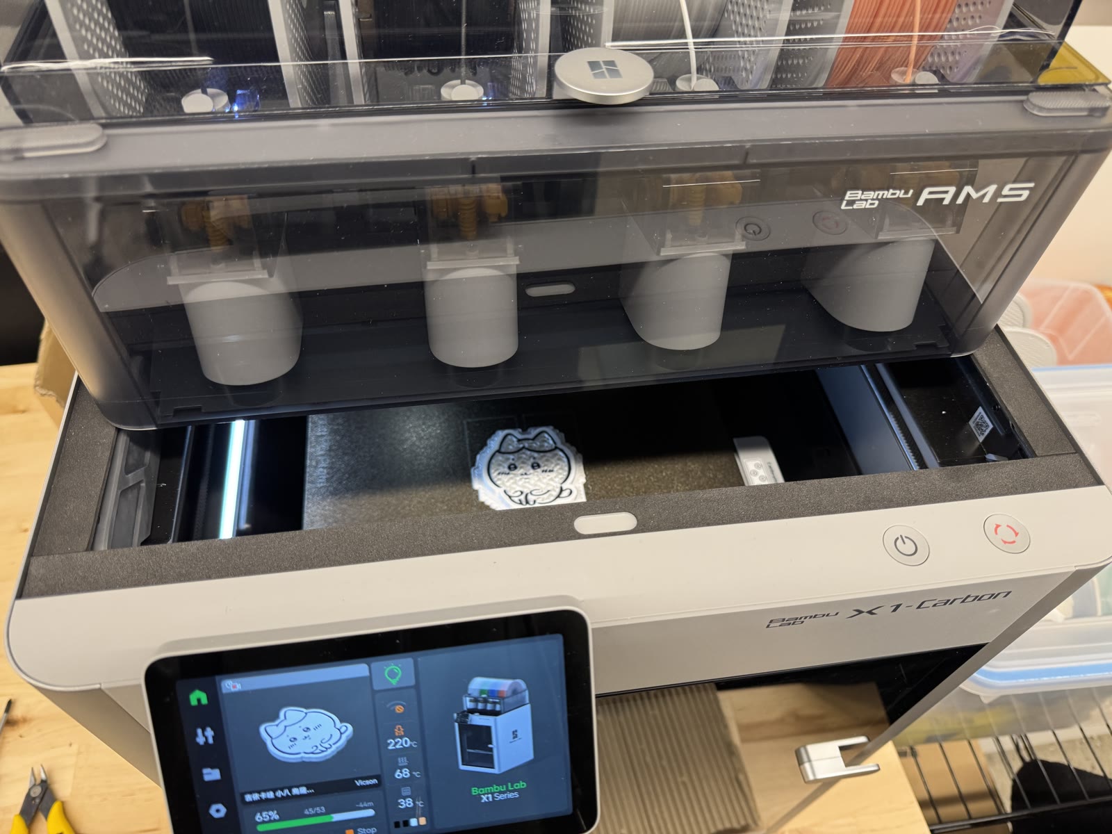
The workflow is CAD model → slicer → printer. We used Bambu Studio to turn the supplied switch-cover model into print instructions for a Bambu Lab printer.
I’ve used Fusion 360 and Bambu Studio before. Below is an earlier Chiikawa print I made with that workflow on a Bambu Lab X1 Carbon.
CO2 laser cutting
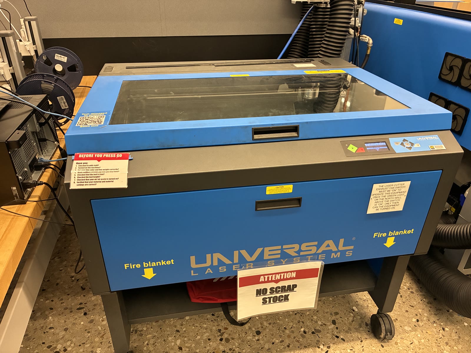
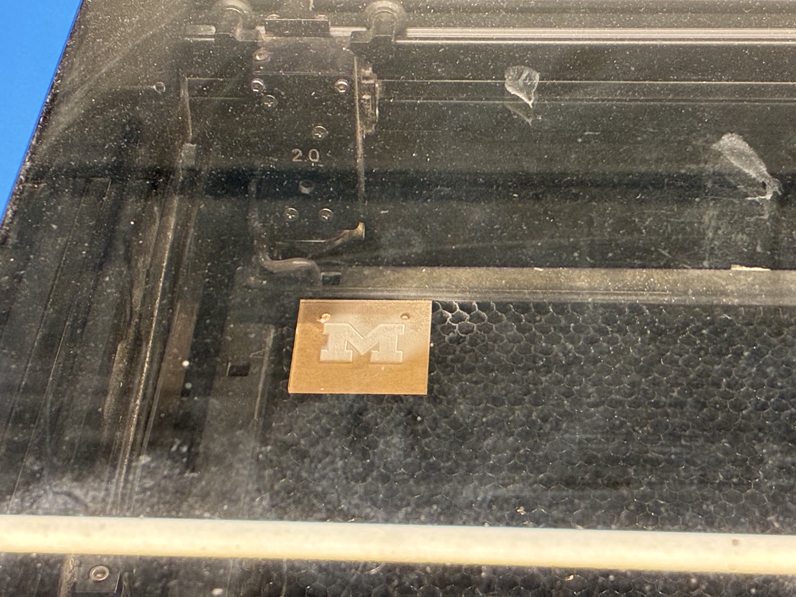
We cut and engraved the acrylic panel on a Universal Laser Systems VLS CO2 laser cutter. Adobe Illustrator is used to prepare the drawing; Universal Control Panel (UCP) handles job settings, previews, and machine control. VLS user guide.
| ULS VLS Laser Cutter | Acrylic Panel in the Machine |
|---|---|
 |
 |
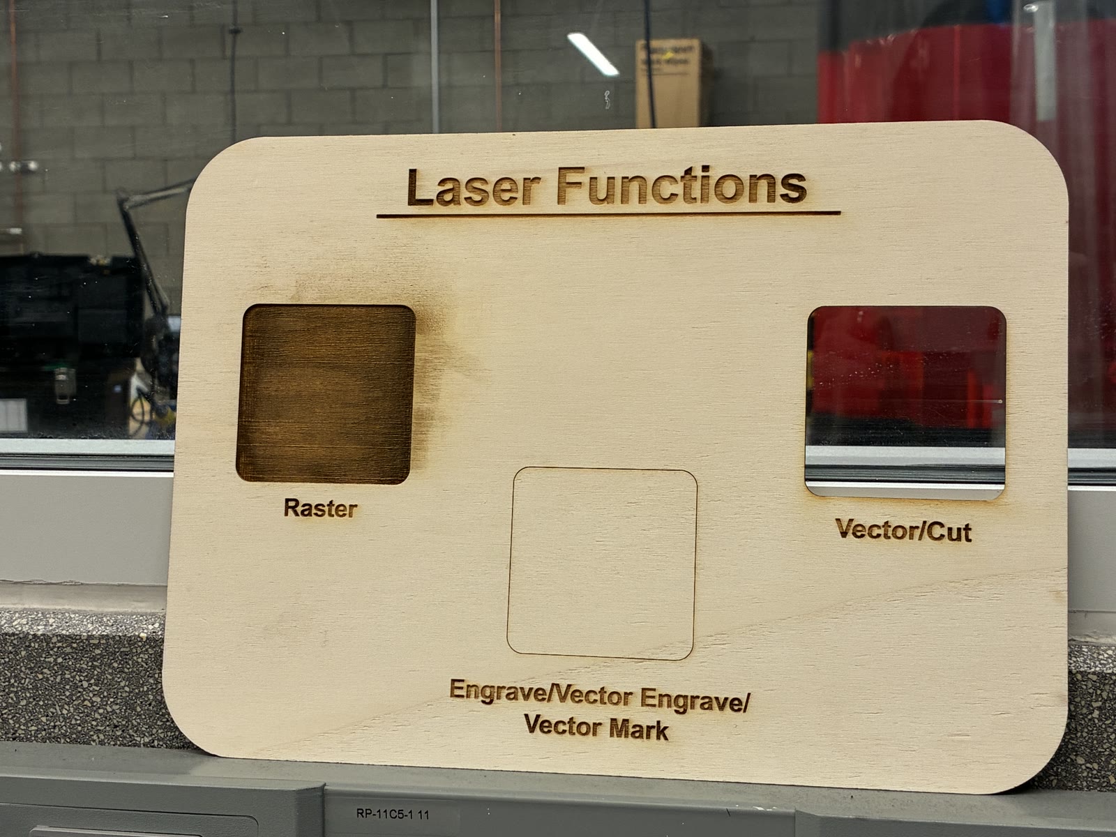
The sample board shows three operations:
- Raster engraving: The laser scans back and forth, removing surface material across a filled area. This works for text, logos, and images, such as the filled “M” on the acrylic panel.
- Line engraving: The laser follows the lines and curves in the drawing, leaving a shallow mark without cutting through. This works for outlines, borders, and reference marks.
- Vector cutting: The laser follows a path with settings that cut through the full material thickness. This creates the part’s outer shape and openings, such as the acrylic panel’s screw holes.
Soldering and assembly
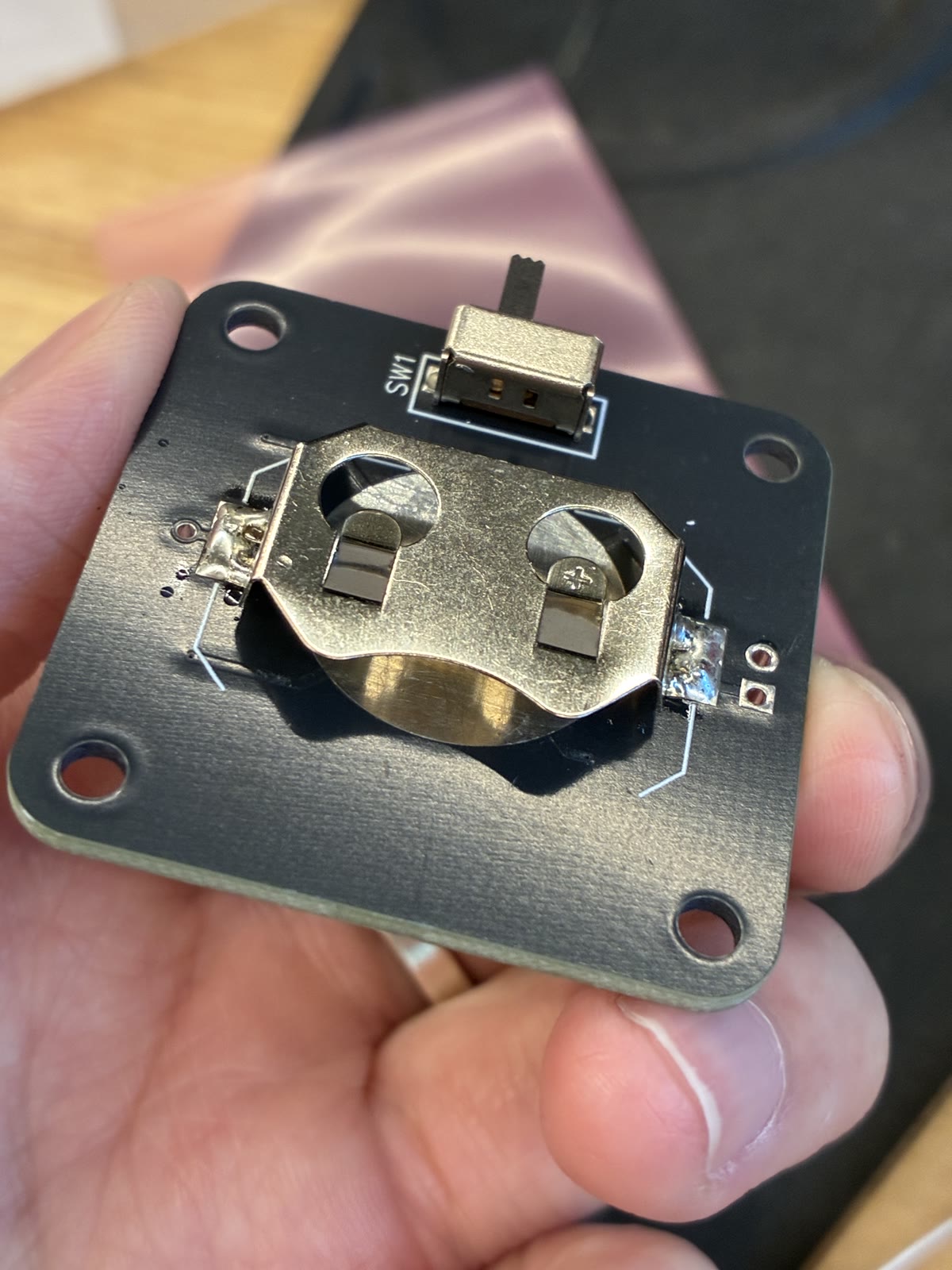
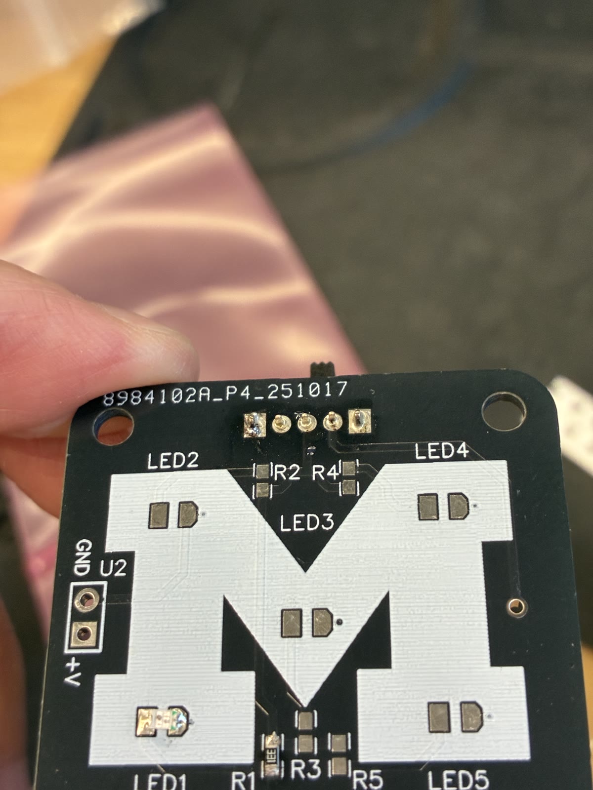
I soldered the LEDs, resistors, switch, and coin-cell battery holder onto the PCB. I had soldered before but hadn’t done it in a while. I messed up the first joint, then got the skill back for the rest.
| Battery Holder and Switch | LEDs and Resistors |
|---|---|
 |
 |
Introduction to Soft Goods
Status: Completed · October 29, 2026
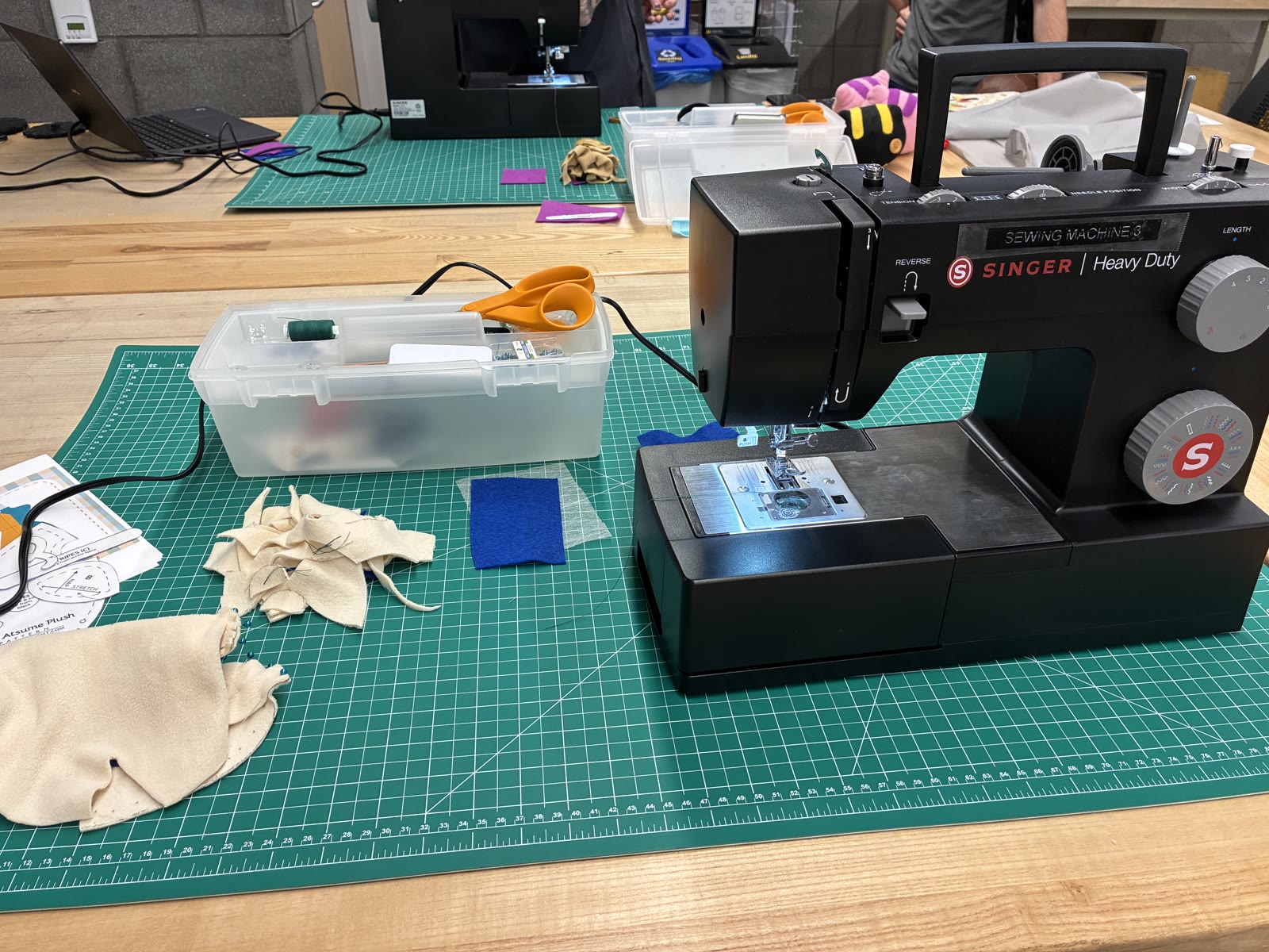
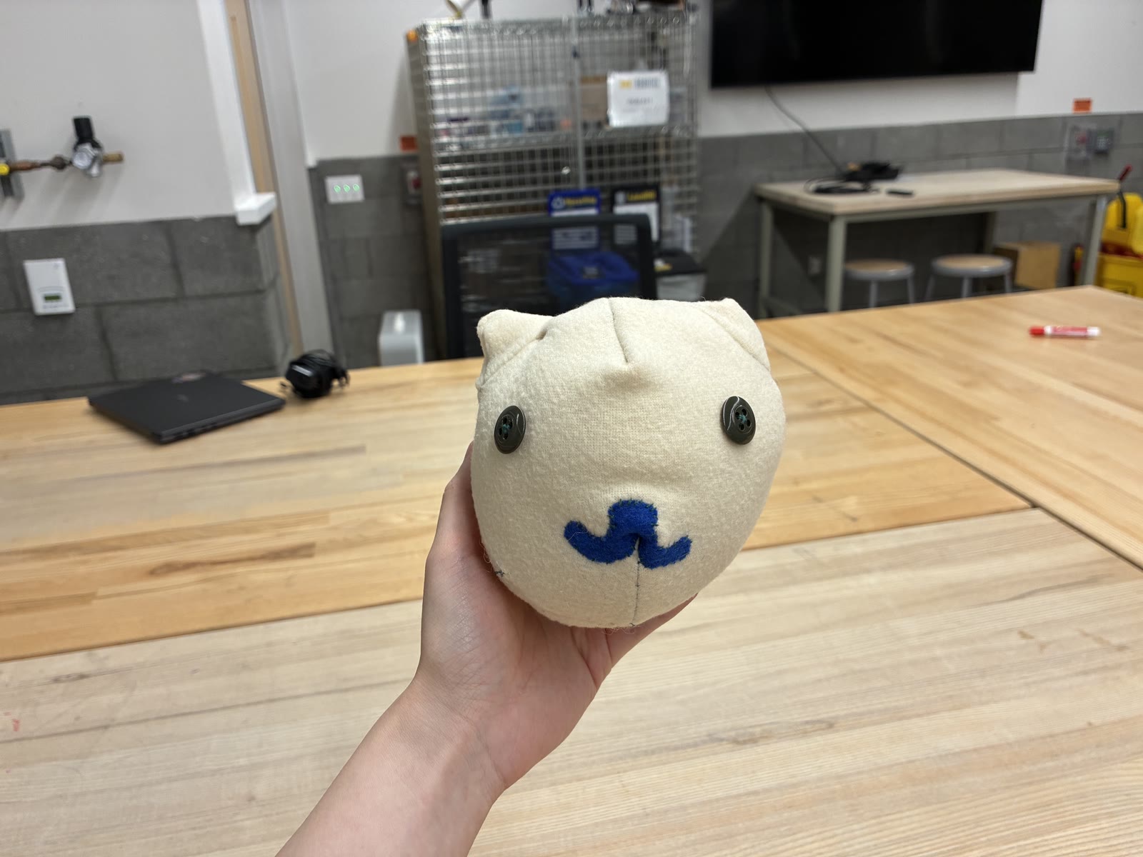
I made a stuffed cat head, practicing hand stitches and using a sewing machine to join the fabric pieces.
| Sewing Setup | Finished Cat |
|---|---|
 |
 |
The whole process took me 3.5 hours:
- Traced the pattern onto the fabric and cut out the front and back of the head, plus the front and back pieces for the ears. Cut the mouth from blue fabric.
- Picked two buttons for the eyes and sewed them onto the front piece. Passed the needle through from the back and through the button holes, making two passes to secure each button.
- Sewed the mouth onto the front piece with a whip stitch.
- Pinned the ears to the front piece and attached them with a running stitch.
- Used the sewing machine to sew the front and back together, leaving an opening for stuffing. Filled the head with cotton and leftover fabric.
- Finally, closed the opening with a ladder stitch, also called an invisible stitch.
Machining
Manual Mill
Location: Wilson Center
Canvas Training: Completed
In-Person Training: Completed · November 11, 2026
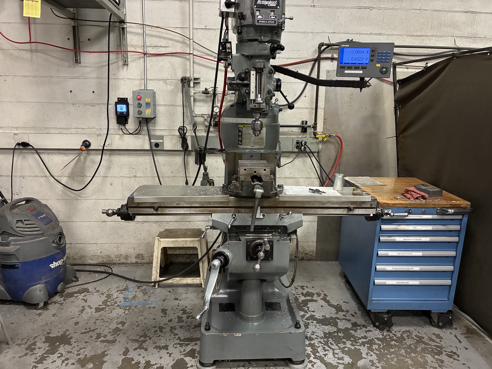
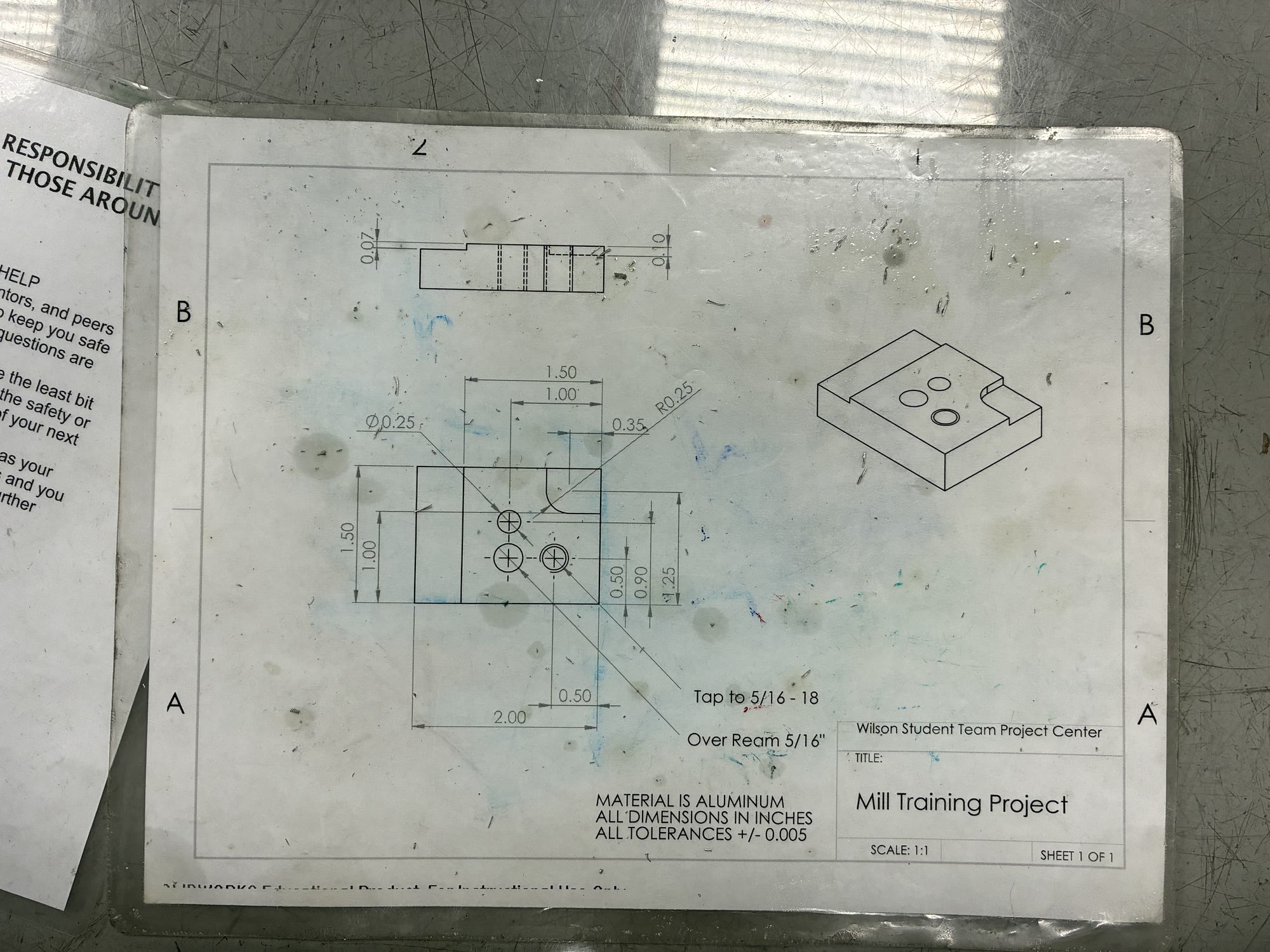
This training used a Bridgeport manual mill to machine an aluminum training part. A manual mill rotates the cutting tool while the workpiece is secured to the table.
| Bridgeport Manual Mill | Training Drawing |
|---|---|
 |
 |
The main tools include:
- Shell Mill: Removes material from a large surface area.
- End Mill: Cuts sideways, and some can plunge vertically.
- Boring Bar: Enlarges an existing hole.
- Drill Chuck: Holds drill bits for drilling, not sideways cutting.
- Auto Drawbar: Tightens and loosens the drawbar for faster tool changes.
To get started, we need to first set zeros. The Digital Readout (DRO) displays the position of each axis. We need to establish the workpiece origin so we can use the DRO to position the cutter according to the drawing.
- For the X/Y axes, the workshop’s DRO only displays X and Y, so we use an edge finder to locate their zero positions.
- Slowly move the spinning edge finder toward the workpiece. When it touches the edge, its tip spins straight, then suddenly deflects to the side. At that point, the spindle center is still one edge finder radius away from the edge, so we need to compensate for that distance. For example, with a 0.100” radius, we can move the spindle center 0.100” toward the edge and then set the DRO to zero, or enter
X = -0.100"when approaching from the negative X direction.
- Slowly move the spinning edge finder toward the workpiece. When it touches the edge, its tip spins straight, then suddenly deflects to the side. At that point, the spindle center is still one edge finder radius away from the edge, so we need to compensate for that distance. For example, with a 0.100” radius, we can move the spindle center 0.100” toward the edge and then set the DRO to zero, or enter
- For Z zero, use the knee and its mechanical dial to touch off on the top surface:
- Slowly raise the knee until the rotating cutter just touches the surface and produces a small chip.
- Set the knee’s dial to zero at that height. This records the surface reference.
- Move the workpiece clear of the cutter before raising the knee by the desired cutting depth. Then feed along X or Y to make the cut.
Reaming improves the size and finish of an existing hole. Use a slower RPM, cutting fluid, and a slow, steady feed without peck drilling.
Tapping creates internal threads in drilled holes. We use a tap guide on the mill to keep the tap aligned, but still turn it manually. Turn approximately one full turn forward and half a turn backward to break the chips.
During training:
- Cut the stock: Used the bandsaw to cut the aluminum to about 1.60 inches, then milled the sawn face to bring that dimension to 1.50 inches.
- Set the origin: Used the edge finder to set the bottom-right corner of the drawing as the X/Y origin. The part lies in the second quadrant, so positions inside it have negative X and positive Y coordinates.
- Mill the side: Fed along Y while machining the side face and learned the difference between conventional milling and climb milling. The finishing pass used climb milling for a smoother surface. The distinction depends on the feed direction relative to cutter rotation at the contact point, not simply positive or negative X/Y. Milling directions.
- Mill the recessed corner: Positioned Y at 1.25 inches on the DRO and established Z zero at the top surface. With the cutter clear of the workpiece, raised the table 0.03 inches, then fed along X to −0.35 inches. The first three passes followed the same route: set Y, feed in along X, then move out along Y. Each removed another 0.03 inches in depth. The final pass removed 0.01 inches, reaching the 0.10-inch recess depth. The 0.03-inch maximum per pass was specific to this exercise.
- Drill and ream: Drilled through the part and reamed the hole that needed a more accurate size and smoother finish. Drilling used a higher spindle speed than reaming. The workshop’s speed chart gave the RPM for each tool and material.
Manual Lathe
Location: Wilson Center
Canvas Training: Completed
In-Person Training: Completed · November 3, 2026
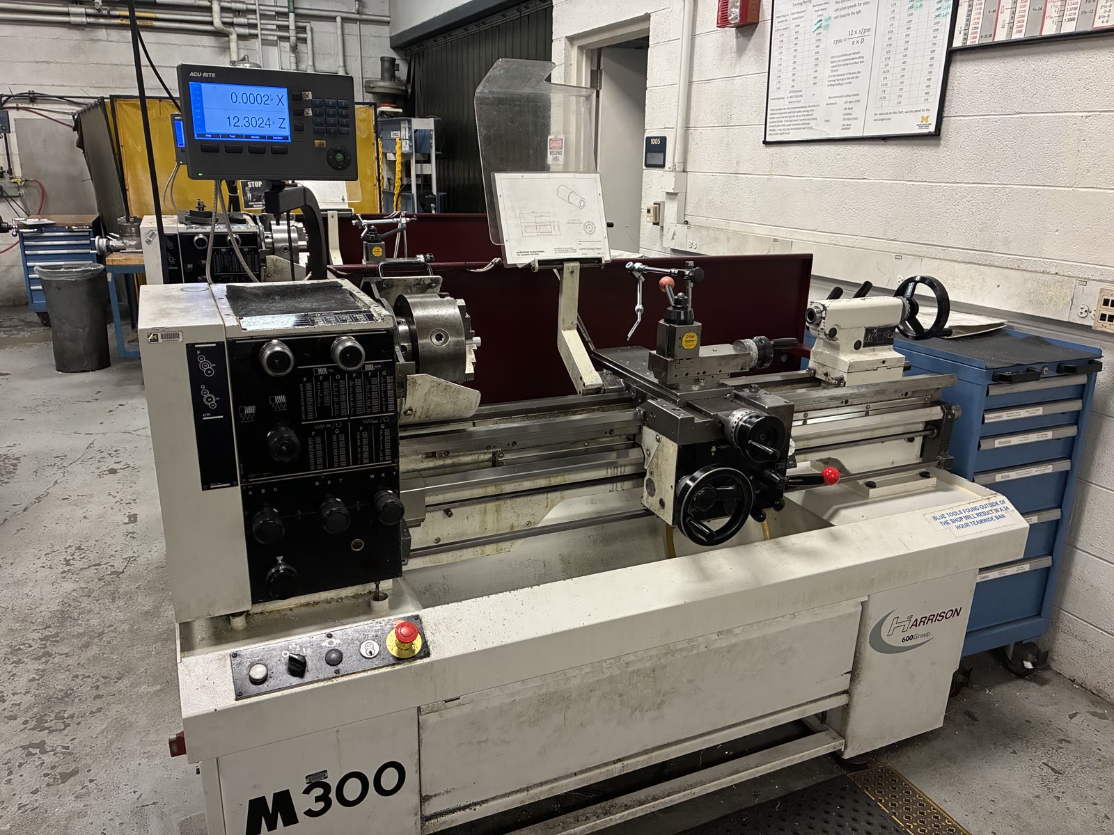
We use a Harrison M300 manual lathe. Unlike a mill where the cutting tool rotates, a lathe rotates the workpiece while the cutting tool removes material.
| Harrison M300 Lathe | Training Drawing |
|---|---|
 |
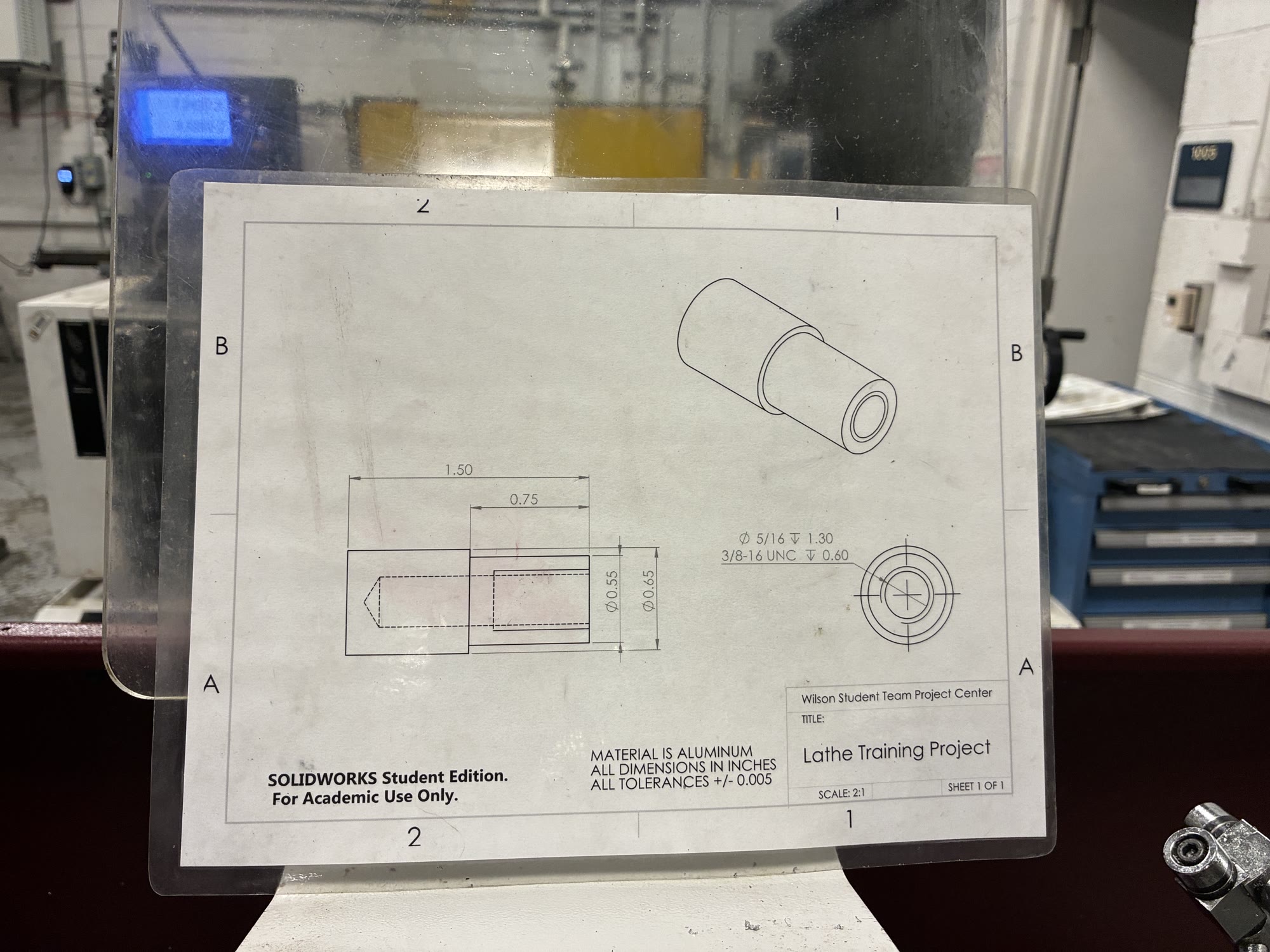 |
Reading the training drawing:
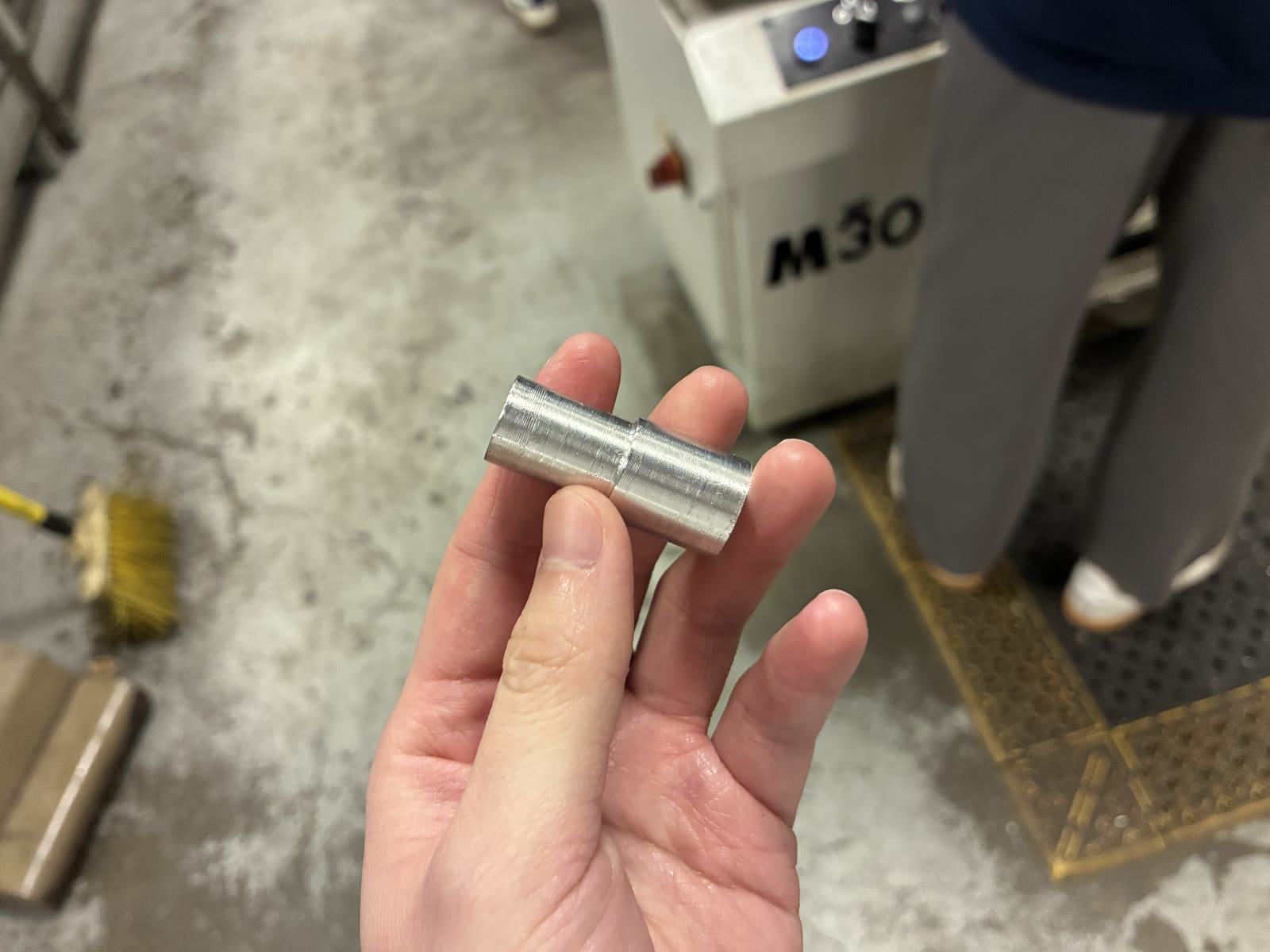
All dimensions are in inches. The part is 1.50 inches long, with a 0.65-inch outer diameter stepped down to 0.55 inches for the last 0.75 inches. The Ø symbol means diameter.
The two lines pointing to the center hole describe drilling and tapping separately:
| Drawing Callout | Meaning |
|---|---|
Ø 5/16, depth 1.30 |
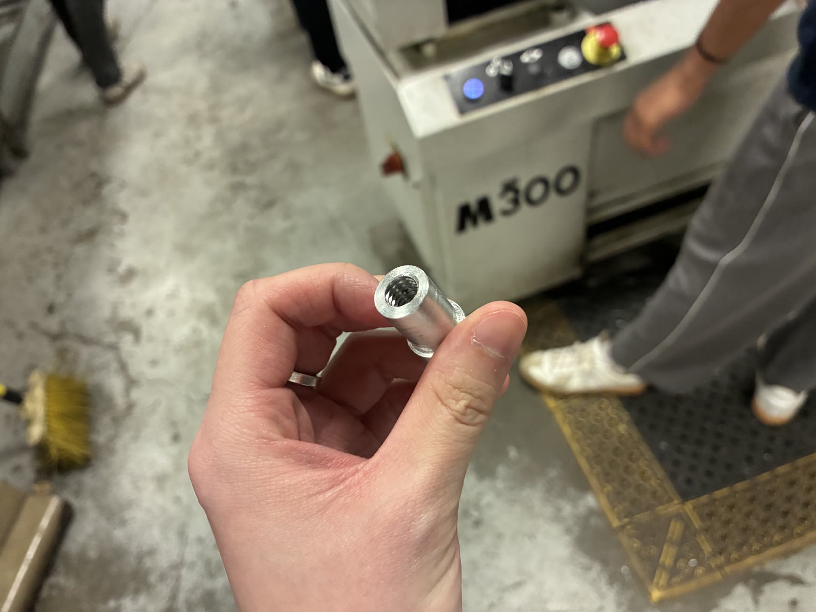
Drill a 5/16-inch hole to the specified 1.30-inch depth. It is a blind hole, so it stops inside the part. |
3/8-16 UNC, depth 0.60 |
Use a 3/8-16 UNC tap to cut 0.60 inches of thread. 3/8 is the nominal thread diameter, 16 means 16 threads per inch, and UNC means Unified National Coarse. |
The lathe has two main axes:
- X-axis: Moves toward or away from the workpiece center, controlling the diameter.
- Z-axis: Moves along the workpiece, controlling the cutting position and length.
Backlash is the small amount of free movement when reversing a handwheel. To maintain accuracy, approach the target position from the same direction.
| Component | Function |
|---|---|
| Chuck | Holds and rotates the workpiece. |
| Saddle | Moves the cutting tool along the Z-axis. |
| Cross Slide | Moves the cutting tool along the X-axis. |
| Compound Rest | Can be rotated for angled cuts. |
| Tool Post | Holds the cutting tool in place. |
| Tailstock | Holds a drill chuck for drilling or a live center for support. |
| Live Center | Supports long workpieces and rotates with them. |
Three common cutting tools:
- Turning Tool: Cuts the Outer Diameter (OD).
- Boring Bar: Enlarges the Inner Diameter (ID) of an existing hole.
- Parting Blade: Cuts a finished part off the stock.
How to set zeros on lathe:
- On a manual mill, we mainly find zero by touching the workpiece. On a lathe, we establish our references by making small cuts.
- Facing: When setting Z, we make a shallow cut across the end face of the workpiece by moving the tool along X-axis. Set
Z = 0on the Digital Readout (DRO), the newly cut face becomes the Z reference for measuring cutting length. - Test cut: When setting X, we make a shallow cut along the workpiece’s outer diameter, then move the tool away along Z without changing X. Measure the new OD with a micrometer and enter that diameter as the X value on the DRO, rather than setting X to zero.
For drilling, the drill bit is held in the tailstock while the workpiece rotates. We use peck drilling and cutting fluid. For larger holes, we can drill a smaller hole first, then enlarge it with a boring bar.
For finishing, the workpiece rotates at a low speed (80–120 RPM) while we use a file to smooth the surface.
Parting uses a parting blade to cut a finished part off the stock. Unlike turning, the blade moves along the X-axis toward the center until the part is separated. If using the paper trick to find the cutting position, also account for the paper thickness (0.003–0.004”).
| Finished Part | Threaded Hole |
|---|---|
 |
 |
Digital Fabrication
Universal R9000
Location: FRB Robotics Makerspace
Status: Completed · October 28, 2026
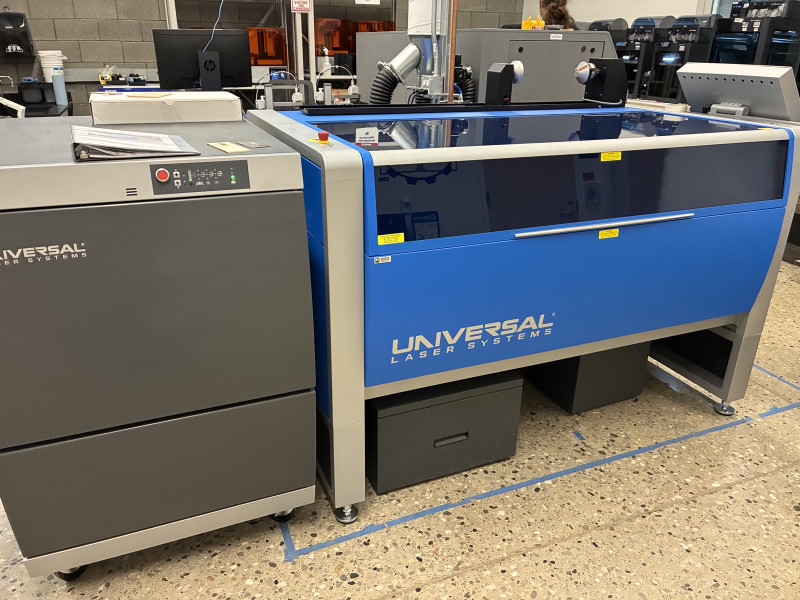
I really enjoyed this workshop. The Universal R9000 feels much more modern than the laser in Basics II. The touchscreen and FRB’s operating handbook made it easy to follow along.
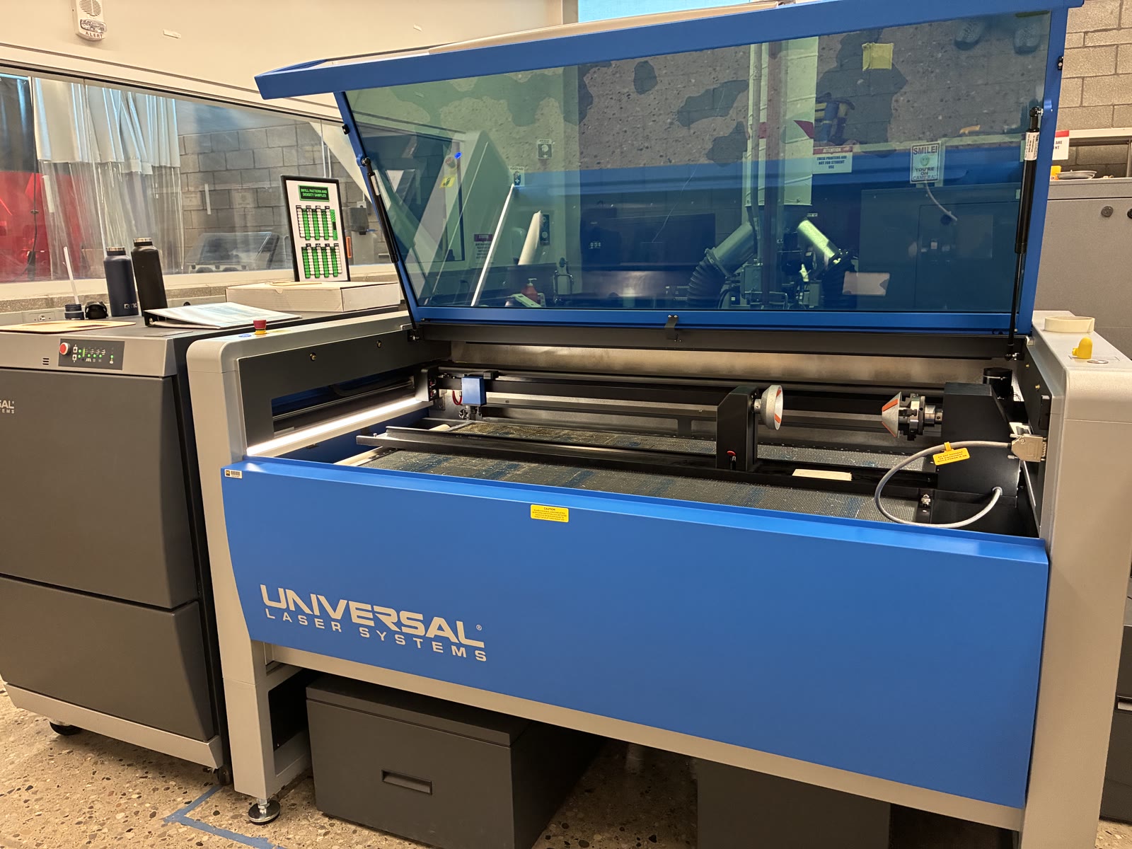
The machine has both CO2 and fiber lasers for cutting and engraving materials such as wood and acrylic, as well as marking metal surfaces. There is also a rotary attachment for engraving cylindrical objects.
| ULTRA R9000 | Rotary Attachment |
|---|---|
 |
 |
There are two cameras. The lid camera gives a bird’s-eye view of the whole work area. The camera on the moving laser head captures a closer view. Both help show where the material is and make it easier to line up the design on it.
The design is loaded from a USB drive through the touchscreen. Drawings can be made in Illustrator and exported as PDFs, a format the machine accepts.
Drawing colors separate the operations. A common convention is:
| Color | Operation | What the laser does |
|---|---|---|
| Black | Raster engraving | Engraves filled areas, such as text and images |
| Red | Cutting | Follows lines to cut through the material |
| Blue | Line engraving | Follows lines to mark the surface without cutting through |
Each color is assigned an operation in the software. These assignments can be changed, as explained in the R9000 user guide.
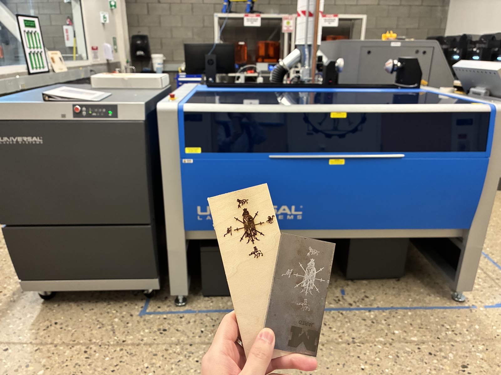
The finished samples below show the same design engraved on wood and marked on metal.
- Very cool design from the instructor Alyssa: the guy in the middle represents a medieval fencing master. The four animals (elephant, lion, lynx, and tiger) represent four qualities of a good fighter. Very interesting and inspiring.
ProtoMAX Waterjet
Location: FRB Robotics Makerspace
Status: Completed · November 3, 2026
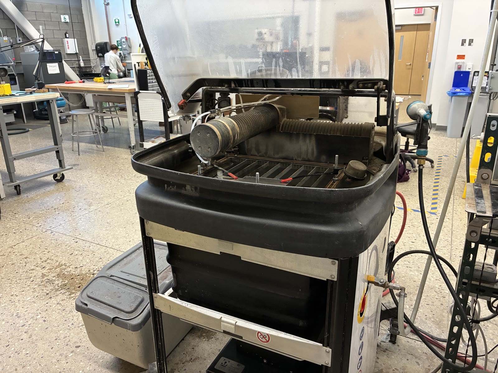
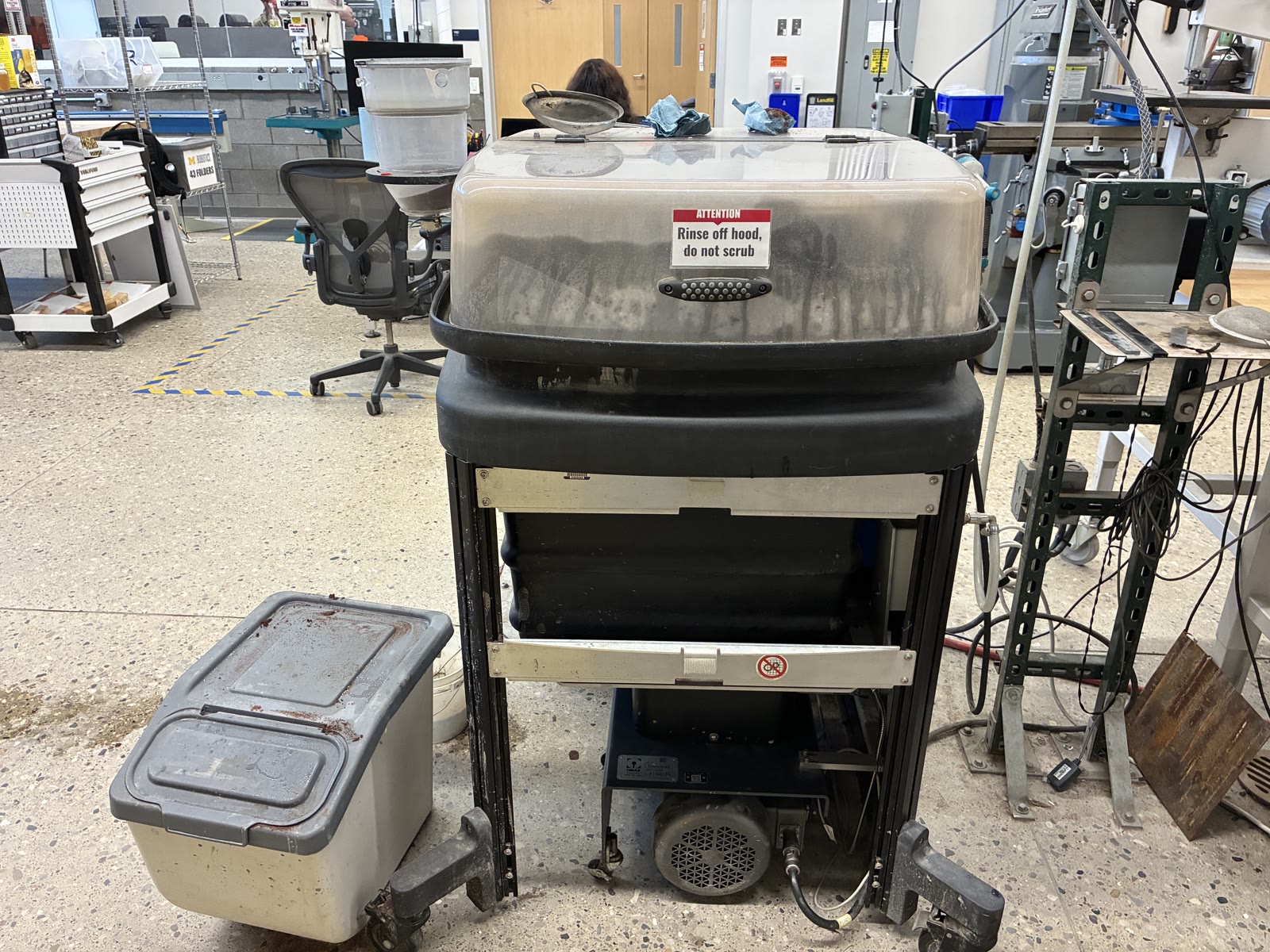
The OMAX ProtoMAX has a 12 × 12 inch cutting area. It cuts with high-pressure water mixed with garnet abrasive, also called media. The plan for this class was to cut a small cat shape from a sheet.
Why use waterjet instead of laser? Abrasive waterjets can cut many materials, including metals, glass, stone, and plastics. They remove material without melting or burning it, so there is no heat-affected zone around the cut. This is useful when heat could damage or distort a part. Laser can be faster for suitable thin sheets, so the choice depends on the material and the job. OMAX comparison.
| Lid Open | Lid Closed |
|---|---|
 |
 |
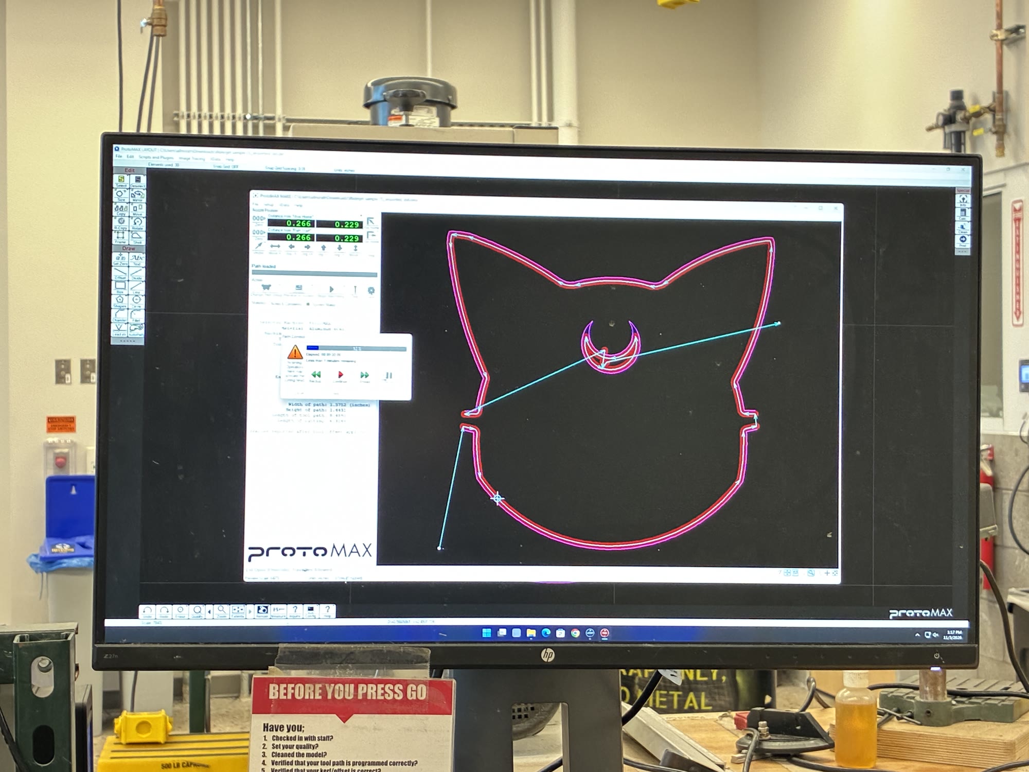
The software workflow is ProtoMAX LAYOUT → ProtoMAX MAKE:
- LAYOUT: Draw a part or import a
.dxffile, add tabs, and generate the toolpath. - MAKE: Preview the toolpath, set the material and thickness, and run the cut. Software guide.
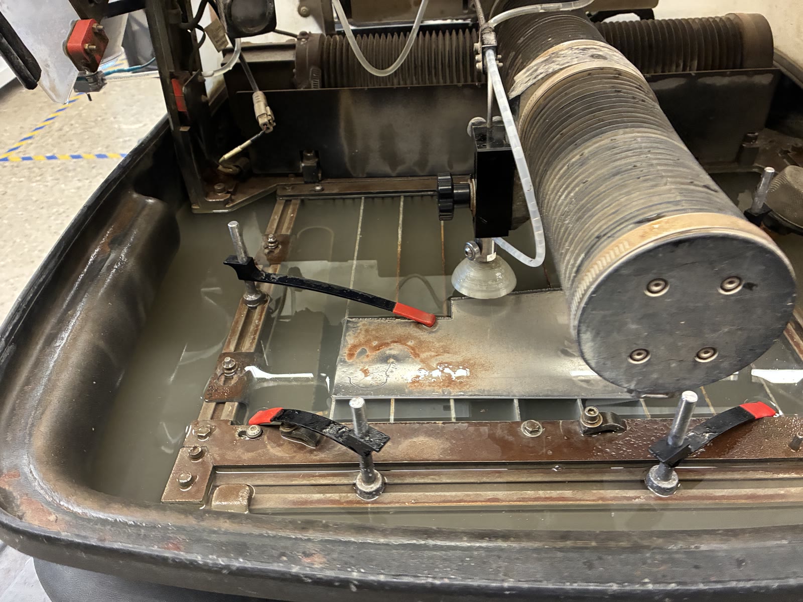
The cat had two tabs, one on each side. These are small bridges of uncut material that keep the part attached to the sheet, preventing it from tipping or falling through the cutting bed. The plan was to drill through the tabs after removing the sheet to free the cat. Tab tool.
With the toolpath ready, the sheet was clamped to the cutting bed and the cut started with the lid closed. It stopped partway through because of a clog. The instructor ended the session so nobody had to keep waiting, leaving the cat unfinished.
| Cat Toolpath | Unfinished Cut |
|---|---|
 |
 |
The abrasive must stay clean and dry until it mixes with water at the nozzle. Moisture in the hopper or feed tube can make it clump and clog, requiring cleaning and drying. ProtoMAX operation guide.
ShopBot CNC Router
Location: Wilson Center
Status: Completed · October 22, 2026
Software: The workflow is CAD → CAM → machine control. Create the design in Fusion 360, then use VCarve Pro to create and preview toolpaths. VCarve also supports drawing simple 2D designs directly. Export a ShopBot .sbp file and load it into ShopBot’s control software. The workshop mainly covers machine operation, so we’ll need to learn more of the software outside.
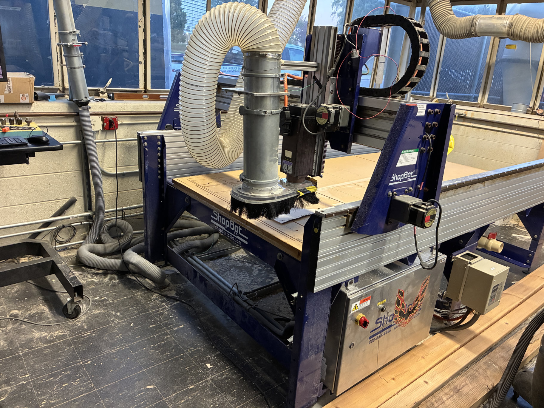
Machine: We use an older ShopBot PRSalpha CNC router. Its spindle moves along X, Y, and Z to cut material on a large bed. The brush skirt and hose collect dust around the cutter.
Setup notes: With the spindle disabled, install the cutter and secure the workpiece. Power on and reset the machine. In keypad mode, arrow keys move X/Y; Page Up/Down move Z. Set the X/Y origin to match the CAM setup. With the cutter installed, use the Z-zero plate to set the tool height from the material or bed surface, matching the CAM setting. Remove the plate and turn on dust collection before cutting.
| ShopBot PRSalpha CNC Router | Router Tools |
|---|---|
 |
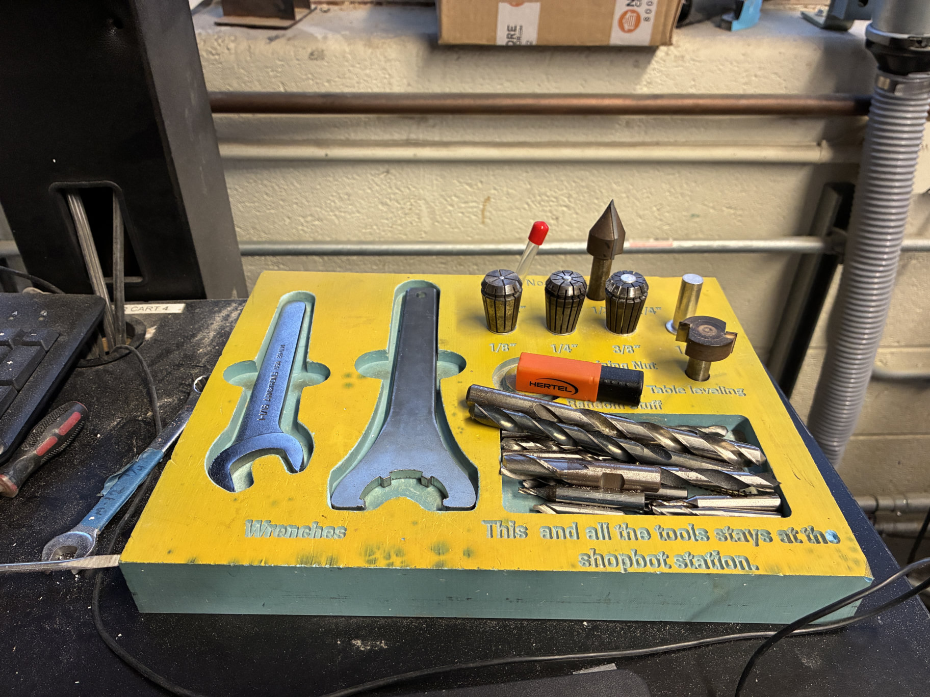 |
Tools in the photo:
- Collets: The slotted sleeves hold different cutter shank sizes in the spindle.
- Wrenches: The smaller wrench holds the spindle shaft; the larger one turns the collet nut to tighten or release the cutter.
- V-bit: The pointed cutter makes V-shaped grooves, lettering, and chamfers.
- Surfacing bit: The wide cutter on the right flattens the spoilboard, the sacrificial board under the workpiece.
- Drill bits and end mills: The tray contains both. Drill bits make holes; end mills cut sideways to make slots, pockets, and outlines.
We were advised to bring our own router bits.
Welding
Location: Canvas
Canvas Training: Completed
Welding training also starts with an online Canvas module, followed by in-person training at the Wilson Center. The module introduces the basics of arc welding.
Welding joins metal parts by using an electric arc to melt the metal at the joint. Shielding gas protects the molten metal from the air, preventing oxidation and porosity (tiny holes in the weld).
There are two main types of welding:
- TIG (Tungsten Inert Gas, or GTAW, Gas Tungsten Arc Welding): Similar to soldering, the electrode and filler metal are separate. A tungsten electrode creates the arc, while a separate filler rod adds material. Unlike soldering, TIG also melts the base metal. It is slower but offers more precise control, making it suitable for thinner materials and detailed work.
- MIG (Metal Inert Gas, or GMAW, Gas Metal Arc Welding): Similar to 3D printing, a metal wire is continuously fed into the weld. The wire acts as both the electrode and filler metal. MIG is generally faster and suitable for larger welds.
TIG 1
Location: Wilson Center
Status: Planned · November 30, 2026
TIG 1 is the prerequisite for the other welding sessions.
Prepping for Welding: Clean metal is important for TIG welding. We use a sand blaster to remove rust, paint, and dirt, followed by a wire wheel to clean the surface. Never wear gloves when using the wire wheel.
Butt Joint: Joins two pieces of metal edge to edge. Thicker materials may need beveled edges and a small gap for better weld penetration. Multiple passes may be needed.
Fixturing and Distortion: Welding creates heat that can cause metal to bend as it cools. Use clamps or jigs to hold the workpiece, distribute heat, and allow cooling between passes.
Duty Cycle: Describes how long a welder can operate without overheating. For example, a 60% duty cycle means 6 minutes of welding and 4 minutes of cooling within a 10-minute period at the rated current.
TIG Torch: Consists of a tungsten electrode, collet, collet body, back cap, and gas cup. The tungsten creates the arc, while the gas cup directs shielding gas around the weld.
Tungsten Sharpening: The tungsten electrode needs a properly shaped tip to maintain a stable arc. We use a tungsten grinder to sharpen the tip when it becomes dull or contaminated.
Welder Setup: Connect the power, ground clamp, foot pedal, and shielding gas. Use AC for aluminum and DC for steel and stainless steel. Set the current and gas flow according to the material and equipment.
How to Weld: Hold the torch like a pencil and keep your hand steady. First, create a weld puddle, then add filler metal with a consistent rhythm.
TIG 2
Location: Wilson Center
Status: Prerequisites not met
MIG Welding
Location: Wilson Center
Status: Prerequisites not met
Aluminum Welding
Location: Wilson Center
Status: Prerequisites not met